Push-along-edge type resistor repair and carving method
A push-type, resistance technology, applied in the direction of resistors, resistance manufacturing, circuits, etc., can solve the problems of sudden change in resistance value, instability, poor resistance to electromagnetic interference, etc., achieve stable working conditions, reduce pulse frequency fluctuations, The effect of improving the anti-electromagnetic interference performance
- Summary
- Abstract
- Description
- Claims
- Application Information
AI Technical Summary
Problems solved by technology
Method used
Image
Examples
Embodiment 1
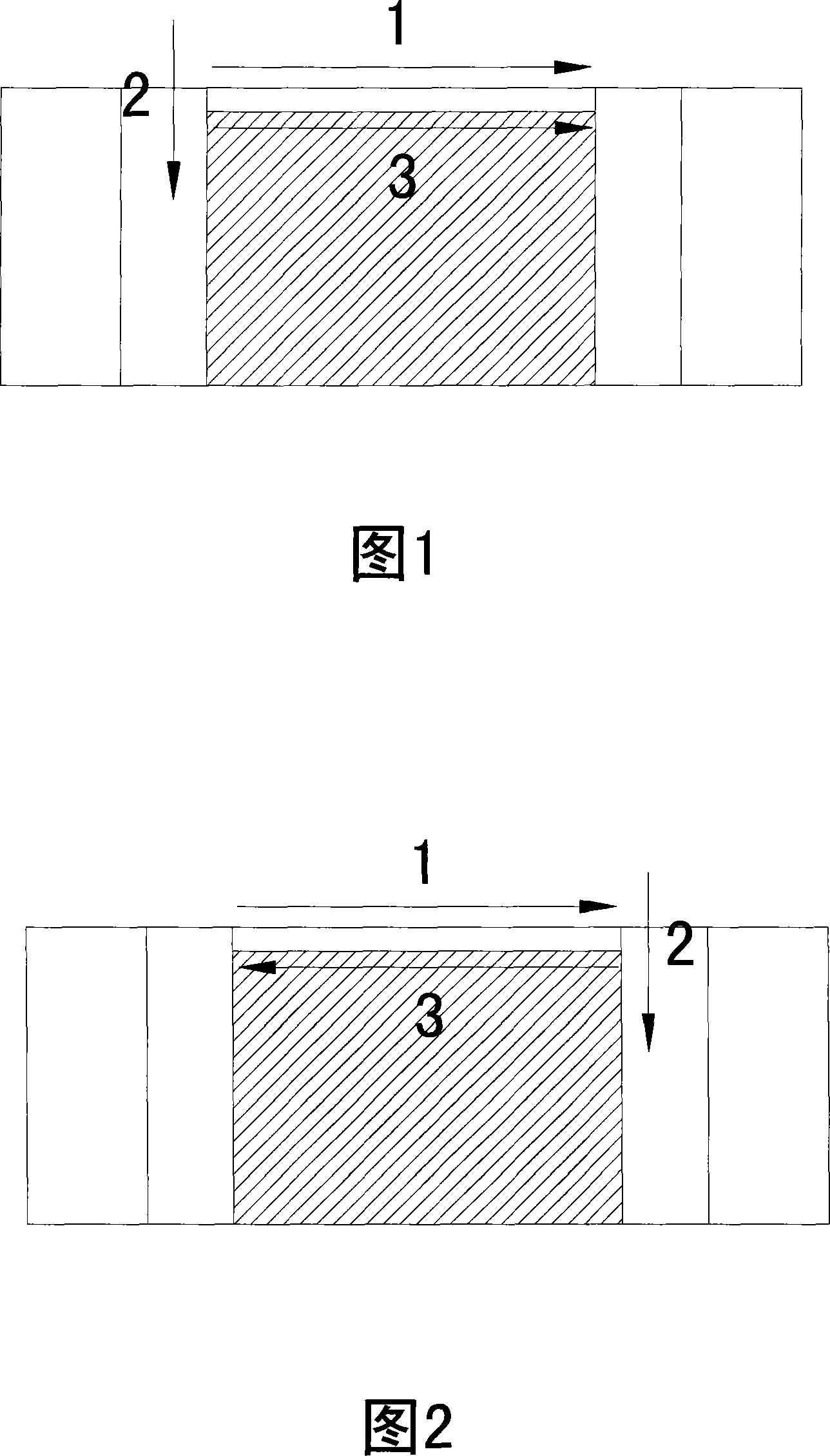
[0024] Embodiment 1: Fig. 1 and Fig. 2 show the specific application of the present invention when repairing and engraving chip resistors. As shown in Figure 1, the current general laser trimming system is adopted, including the laser beam generated by the Nd:YAG laser, which is expanded by the beam positioning system and focused on the fixed resistor to be engraved at the focal plane position in the workbench. The dynamic measurement system monitors in real time and outputs feedback control signals to the laser trimming setter program to change the Q frequency, etching size and cutting trimming direction, and automatically correct it; control the laser beam alternately to perform the following two steps when feeding: 1) Take the intersection point of the upper edge curve and the left edge curve of the chip resistor as the starting point, and the width of the laser beam as the width; etch along the upper edge curve track, and the etching movement track is a straight line as sho...
Embodiment 2
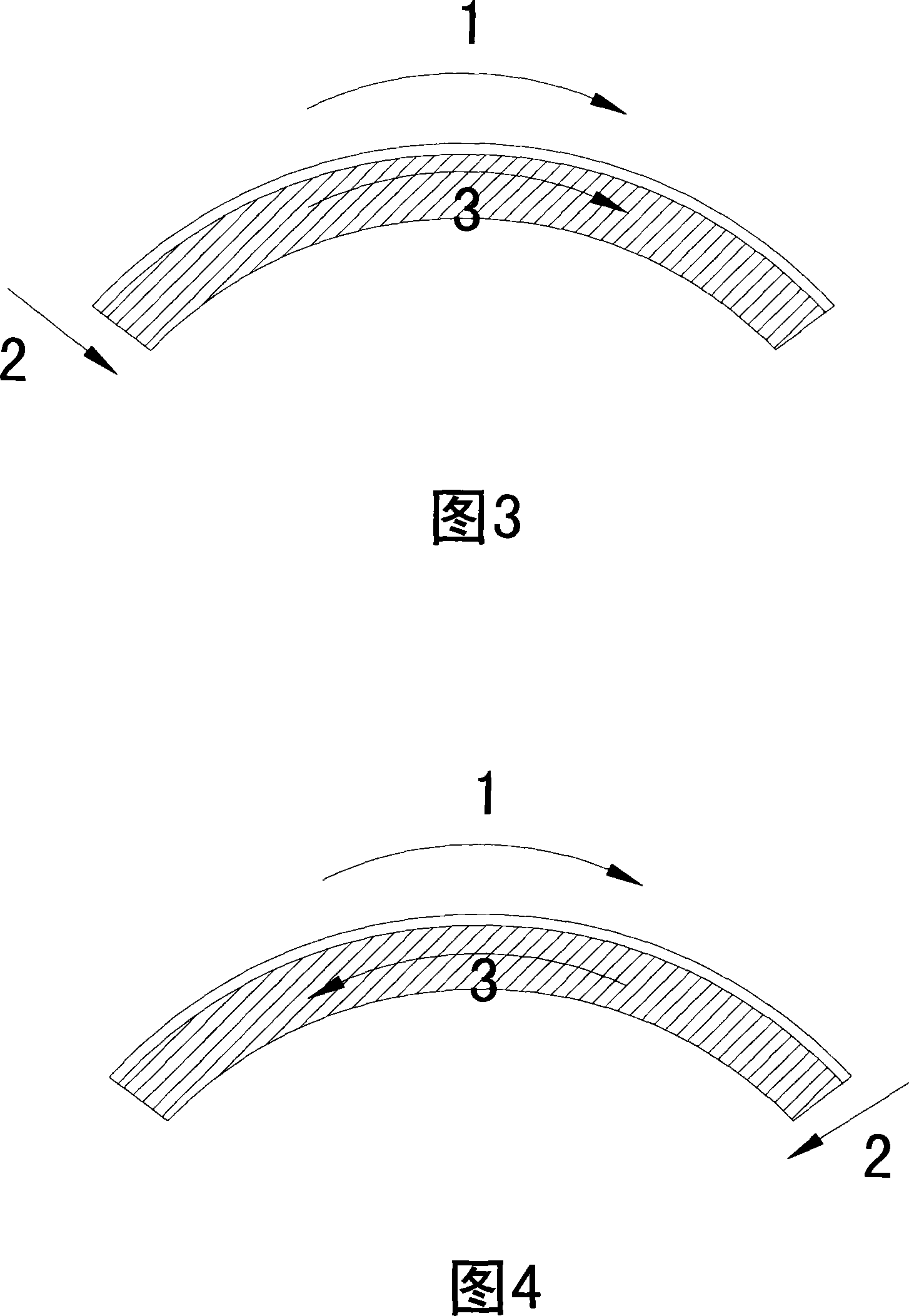
[0026]Embodiment 2: Fig. 3 and Fig. 4 show the specific application of the present invention when repairing and engraving arc resistance. As shown in Figure 2, the current general laser trimming system is adopted, including the laser beam generated by the Nd:YAG laser, which is expanded by the beam positioning system and focused on the fixed resistor to be engraved at the focal plane position in the workbench. The dynamic measurement system monitors in real time and outputs feedback control signals to the laser trimming setter program to change the Q frequency, etching size and cutting trimming direction, and automatically correct it; control the laser beam alternately to perform the following two steps when feeding: 1) Take the intersection point of the upper arc edge curve and the left edge curve of the arc-shaped resistor as the starting point, and the width of the laser beam as the width; etch along the upper edge curve, and the etching movement track is shown as an arc as ...
Embodiment 3
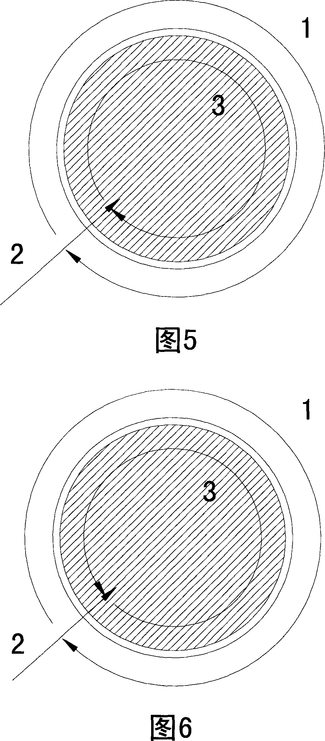
[0028] Embodiment 3: Fig. 5 and Fig. 6 show the specific application of the present invention when repairing and engraving circular resistors. As shown in Figure 5, the current general-purpose laser trimming system is adopted, including the laser beam generated by the Nd:YAG laser, which is expanded by the beam positioning system and focused on the fixed resistor to be engraved at the focal plane position in the workbench. The dynamic measurement system monitors in real time and outputs feedback control signals to the laser trimming setter program to change the Q frequency, etching size and cutting trimming direction, and automatically correct it; control the laser beam alternately to perform the following two steps when feeding: 1) Take any point on the outer circumference of the circular resistor as the starting point, and the width of the laser beam as the width, etch clockwise along the curved track of the outer circumference for one week and return to the starting point (s...
PUM
 Abstract
Description
Claims
Application Information
 - R&D
- Intellectual Property
- Life Sciences
- Materials
- Tech Scout
- Unparalleled Data Quality
- Higher Quality Content
- 60% Fewer Hallucinations
Browse by: Latest US Patents, China's latest patents, Technical Efficacy Thesaurus, Application Domain, Technology Topic, Popular Technical Reports.
© 2025 PatSnap. All rights reserved.Legal|Privacy policy|Modern Slavery Act Transparency Statement|Sitemap|About US| Contact US: help@patsnap.com


