Real-time braking distributing device and method for motor vehicle

A distribution device and braking force technology, applied in the direction of brakes, etc., can solve the problems of not being able to adjust the braking force of the front and rear axles in real time, not being able to make full use of the adhesion of the front wheels, and the braking distance of motor vehicles becoming longer, so as to achieve a method of controlling distribution Simplicity, prevention of tail drift and sideways movement, and short braking distance

Active Publication Date: 2007-12-19
BYD CO LTD
View PDF0 Cites 15 Cited by
  • Summary
  • Abstract
  • Description
  • Claims
  • Application Information

AI Technical Summary

Problems solved by technology

When a motor vehicle brakes on a road with a relatively good adhesion coefficient at a certain deceleration, the load transfer will make the front axle load greater than the rear axle load. However, the existing EBD cannot change the load according to the deceleration and the resulting load. And adjust the braking force of the front and rear axles in real time
It only reduces the braking force when the rear wheels are about to be locked, but does not respond to the increase in front axle load, and increases the braking force of the front wheels accordingly. As a result, the adhesion of the front wheels cannot be fully utilized, and the braking distance of the motor vehicle lengthen

Method used


Image

  • Real-time braking distributing device and method for motor vehicle
  • Real-time braking distributing device and method for motor vehicle
  • Real-time braking distributing device and method for motor vehicle

Examples


Embodiment Construction

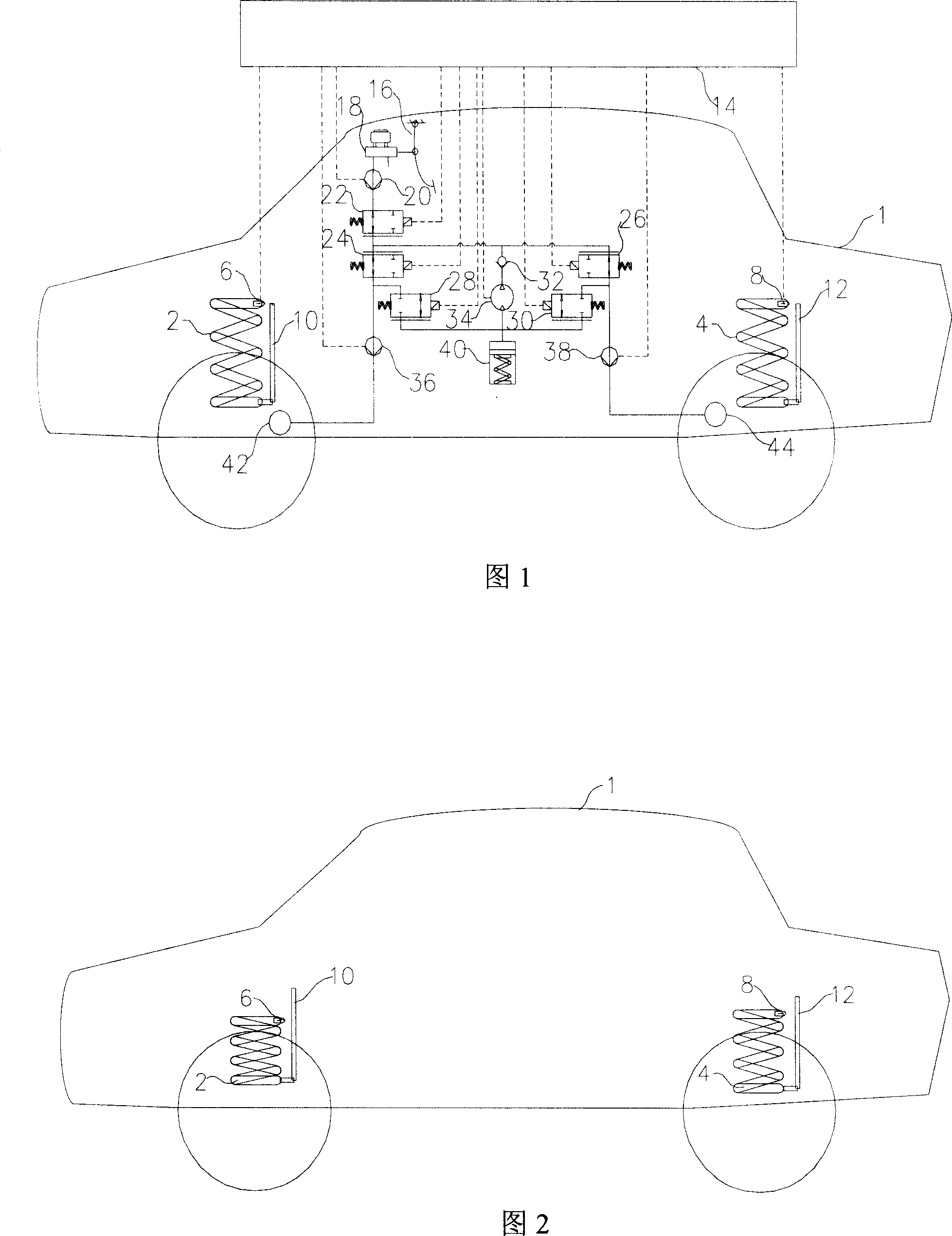
[0038] The structure of the specific embodiment of the device of the present invention is shown in FIG. 1 . Including motor vehicle body 1, front suspension spring 2, detection head 6 of front suspension displacement sensor, fixed part 10 of front suspension displacement sensor, rear suspension spring 4, detection head 8 of rear suspension displacement sensor, rear suspension Fixed part 12 of frame displacement sensor, electronic control unit 14, brake pedal 16, brake master cylinder 18, brake master cylinder pressure sensor 20, normally open valve 22, front wheel brake force control valve 24, front brake wheel cylinder drain Pressure valve 28, front brake wheel cylinder pressure sensor 36, front brake wheel cylinder 42, rear wheel brake force control valve 26, rear brake wheel cylinder pressure relief valve 30, rear brake wheel cylinder pressure sensor 38, rear brake wheel cylinder 44, single To valve 32, hydraulic pump 34 and reservoir 40.

[0039] The upper end of front su...


PUM


Abstract

The present invention discloses real-time braking force distributing device and method for motor vehicle. The real-time braking force distributing device includes one front suspension displacement sensor and one rear suspension displacement sensor for detecting the compression deformations of the front and the back suspension springs separately, and one electronic control unit to accept the detected compression deformations. The real-time braking force distributing method includes the following steps: 1. entering to the main control process to calculate the load ratio between front and rear wheels; 2. recognizing whether the vehicle to be in brake state and selecting whether to enter the braking force distribution; and 3. recognizing whether the vehicle to be in emergency brake state, selecting the boost control sub-process or decompression control sub-process and controlling the front-to-rear braking pressure ratio to equal to the load ratio. The present invention can ensure smooth and safe running.

Description

technical field [0001] The invention relates to the field of motor vehicle braking, in particular to a device and method for real-time distribution of braking force of a motor vehicle. Background technique [0002] Since the front and rear tires of a motor vehicle adhere to different conditions on the ground, it is easy to cause slipping, tilting and rollover due to the different friction between the tires and the ground during braking. System, abbreviated as ABS) motor vehicles, generally use electronic brake force distribution device (Electric Brake force Distribution, abbreviated as EBD) as an auxiliary part of ABS, improve the efficacy of ABS, to ensure the driving safety of motor vehicles. When a motor vehicle brakes on a road with a relatively good adhesion coefficient at a certain deceleration, the load transfer will make the front axle load greater than the rear axle load. However, the existing EBD cannot change the load according to the deceleration and the resultin...

Claims


Application Information

Patent Timeline
Patent Type & Authority Applications(China)
IPC IPC(8): B60T8/18
Inventor 宋佑川王国保胡庚伟
Owner BYD CO LTD
Why Eureka
Try Eureka