High pressure operation quick release rectification circuit

A rectifier circuit, high-voltage technology, applied in the direction of electromagnets, electrical components, electromagnets with armatures, etc., can solve the problems of affecting the starting and stopping performance of the motor, affecting the service life of the motor, and low voltage at both ends of the brake coil.

Inactive Publication Date: 2007-12-19
赵维国
View PDF0 Cites 6 Cited by
  • Summary
  • Abstract
  • Description
  • Claims
  • Application Information

AI Technical Summary

Problems solved by technology

[0003] However, the existing rectifier circuit of the electromagnetic brake generally adopts a unidirectional diode to control the unidirectional conduction of the current. The voltage at both ends of the brake coil is relatively low, and the armature pull-in speed is slow; at the same time, when the motor loses power, the brake will also have a certain time delay before braking, and the release speed of the armature is also slow, which not only affects the motor. Stop performance, and in the long run, will affect the service life of the motor

Method used


Image

  • High pressure operation quick release rectification circuit
  • High pressure operation quick release rectification circuit

Examples


Embodiment Construction

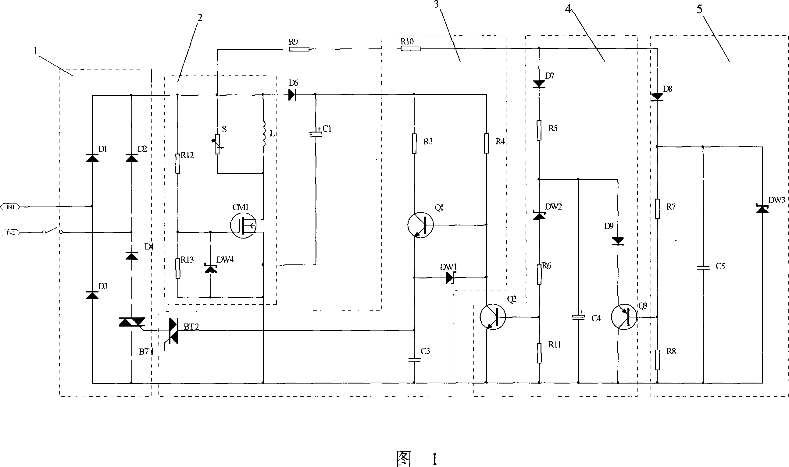
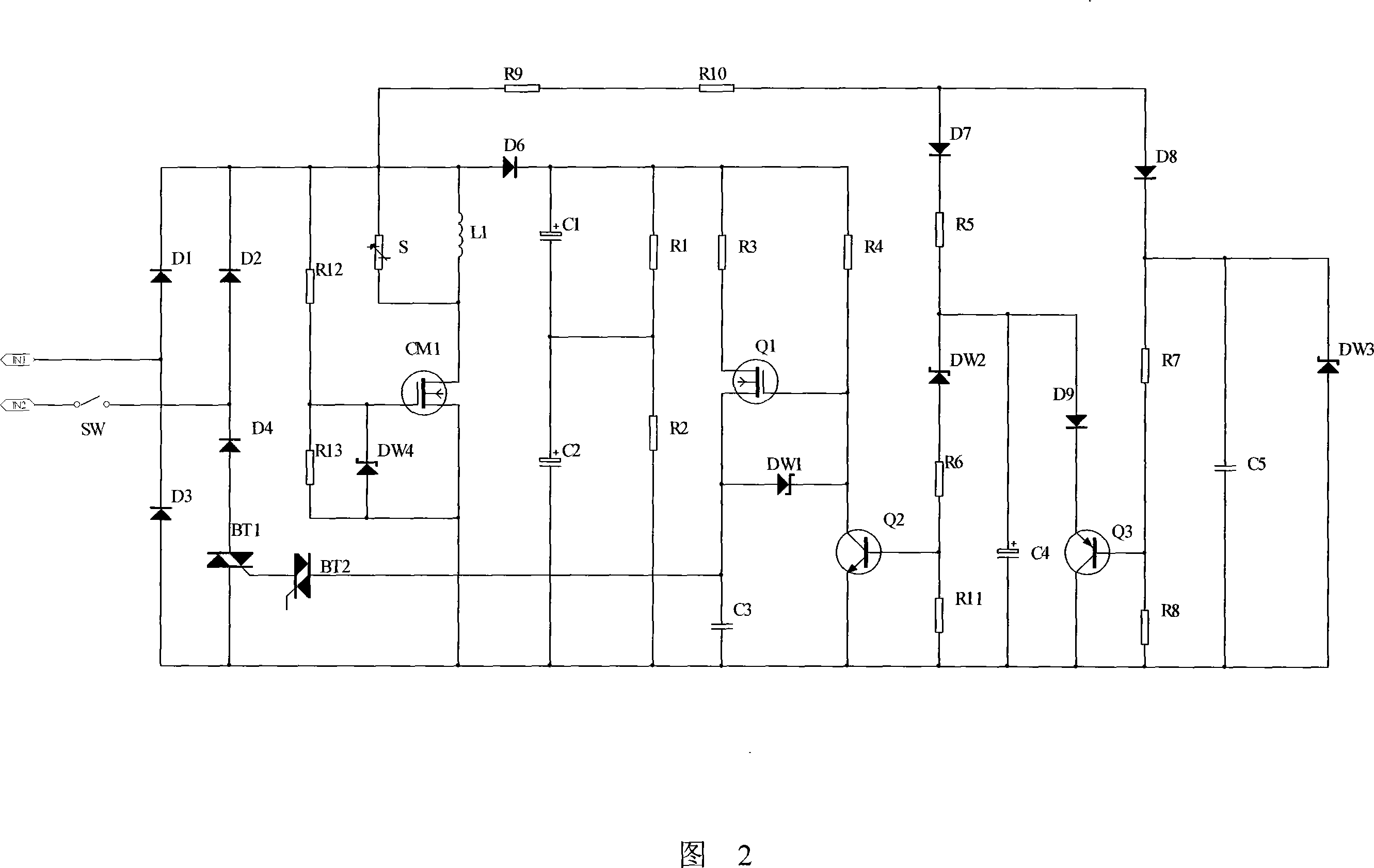
[0017] As shown in Figure 1, the high-voltage pull-in quick-release rectifier circuit shown in the first embodiment of the present invention, the power supply voltage of the motor in this embodiment is 220V, the high-voltage pull-in quick-release rectifier circuit includes a bridge rectifier circuit 1, and the bridge A high-voltage pull-in circuit 2 connected in parallel with a type rectifier circuit, a trigger circuit 3 and a timing circuit 4.

[0018] The rectifier circuit 1 rectifies the alternating current input by the motor into direct current and supplies it to the brake or clutch (the brake is taken as an example below). The input terminal of the rectifier circuit 1 is connected to the motor power switch SW, including diodes D1, D2, D3, D4 and bidirectional The bridge rectifier circuit composed of thyristor BT1, in other embodiments, triac BT1 may also be a unidirectional thyristor. The rectifier circuit 1 also includes a parallel filter circuit, which is composed of a ...


PUM


Abstract

This invention relates to a high voltage pick-up quick discharge commutation circuit including a commutation circuit, a high voltage pick-up circuit parallel to the commutation circuit, a trigger circuit and a timing circuit, in which, the input of the commutation circuit is connected to the supply switch of a motor, said pick-up circuit includes a field effect tube and an output coil, said trigger circuit includes a trigger diode and a first triode providing a trigger signal to the trigger diode, the timing circuit provides the delay time from high voltage piock up to normal work, at the instance when the motor switch is turned off, said trigger diode is triggered, the voltage of the two ends of the output coil is high, that is the high voltage pick-up and the working voltage of the two ends of the coil is the relative low voltage.

Description

technical field [0001] The invention relates to the field of motor control, in particular to a rectification control circuit for controlling the engagement and release of a motor clutch or brake. Background technique [0002] At present, most of the three-phase AC motors used in chemical industry, construction, machine tools and other fields use electromagnetic clutches and brakes to control the pull-in and release of the armature. Taking the electromagnetic brake as an example, when the motor is energized, the brake rectifies the alternating current into direct current through the rectifier circuit. At this time, the armature is attracted under the action of the electromagnetic field, so that the brake disc is in a rotatable state and the motor rotates freely; When the motor loses power, the armature is supported by the spring, so that the brake disc and the rear end cover of the motor are pressed together and stop rotating. [0003] However, the existing rectifier circuit...

Claims


Application Information

Patent Timeline
Patent Type & Authority Applications(China)
IPC IPC(8): H01F7/18H02M7/155
Inventor 李晓娥王兴波
Owner 赵维国
Why Eureka
Try Eureka