

Transformer
A technology of transformers and conductors, applied in the field of transformers, can solve problems such as reducing the coupling degree of windings, and achieve the effects of improving efficiency, high coupling degree, and high current density
- Summary
- Abstract
- Description
- Claims
- Application Information
AI Technical Summary
Problems solved by technology
Method used
Image

Examples
Embodiment Construction
[0049] A transformer according to a preferred embodiment of the present invention will be described below with reference to related drawings, wherein the same elements will be described with the same reference symbols.
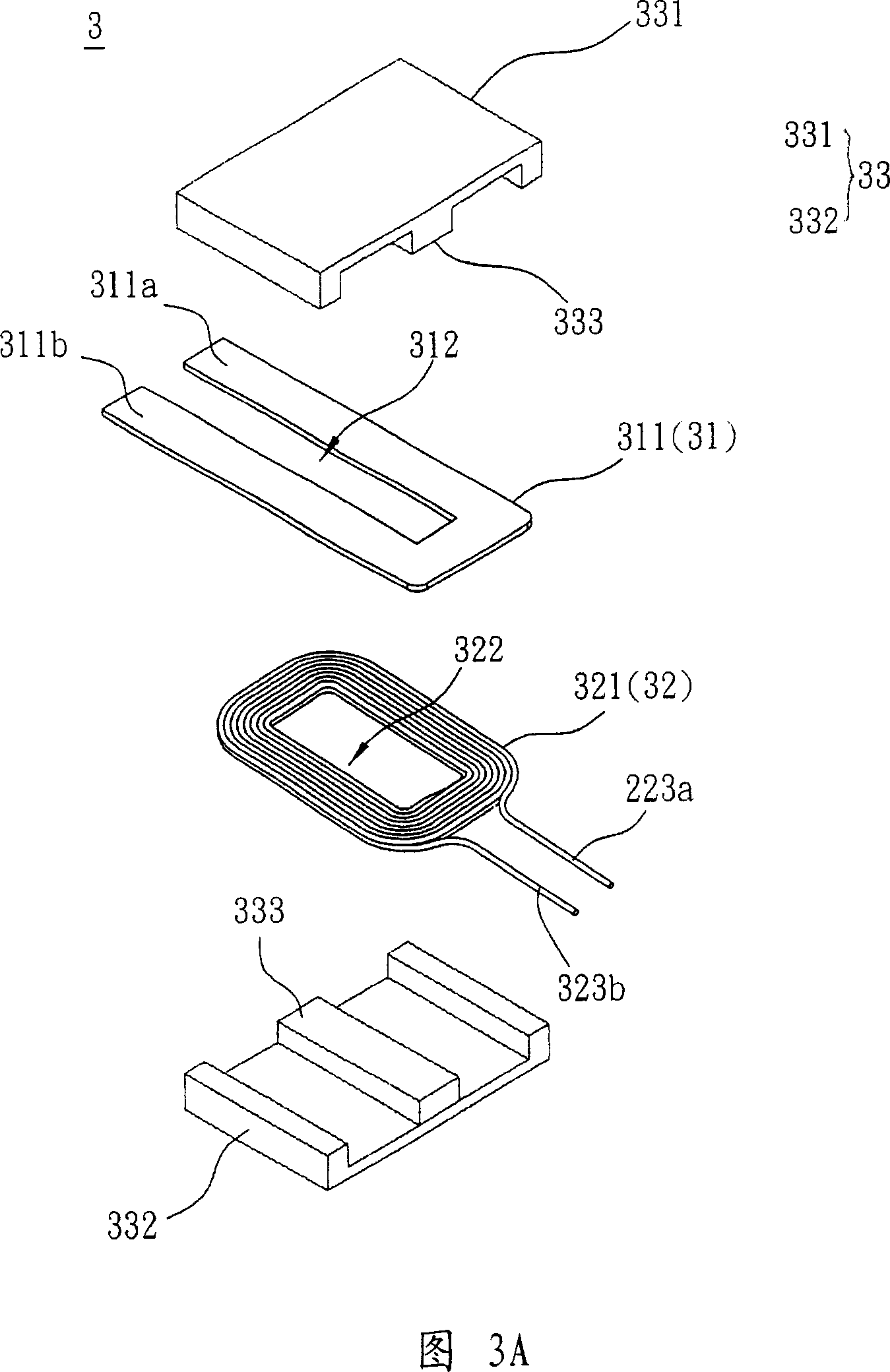
[0050] Please refer to FIG. 3A and FIG. 3B at the same time, which is a schematic diagram of a transformer according to a preferred embodiment of the present invention. A transformer 3 according to a preferred embodiment of the present invention includes a first conductor 31 , a second conductor 32 and an iron core 33 . The transformer 3 of this embodiment can be used to modulate the voltage or current of a power supply.
[0051] The first conductor 31 includes at least one conductive sheet 311 , the second conductor 32 includes at least one multilayer spiral coil 321 , and the first conductor 31 and the second conductor 32 are electromagnetically coupled. In this embodiment, the conductive sheet 311 can be a copper sheet.
[0052] The multi-layer spiral coi...
PUM
 Abstract
Description
Claims
Application Information