
Generator for automobile

A technology for alternators and vehicles, applied in engine-driven traction, applications, electromechanical devices, etc., which can solve problems such as deterioration of radiator cooling performance and temperature rise of voltage regulators, and achieve the goal of suppressing temperature rise and expanding the installation area Effect

Inactive Publication Date: 2007-12-19
MITSUBISHI ELECTRIC CORP
View PDF1 Cites 3 Cited by
  • Summary
  • Abstract
  • Description
  • Claims
  • Application Information

AI Technical Summary

Problems solved by technology

Because of this, the cooling air cannot sufficiently flow into the ventilation path between the cooling fins of the radiator of the voltage regulator, which deteriorates the cooling performance of the radiator and causes the temperature of the voltage regulator to rise.

Method used


Image

  • Generator for automobile
  • Generator for automobile
  • Generator for automobile

Examples


Embodiment Construction

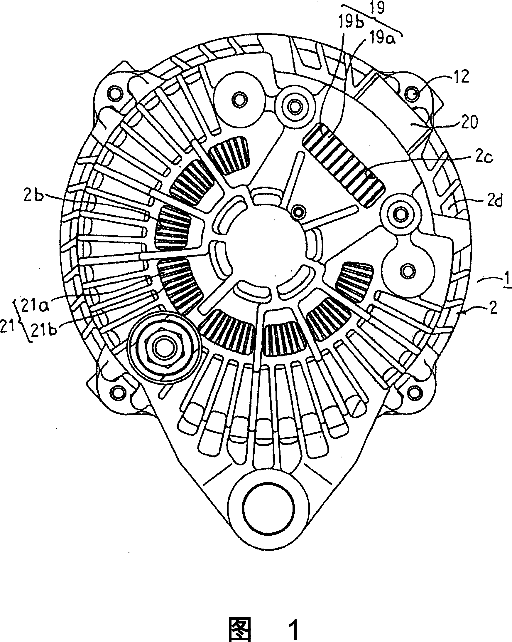
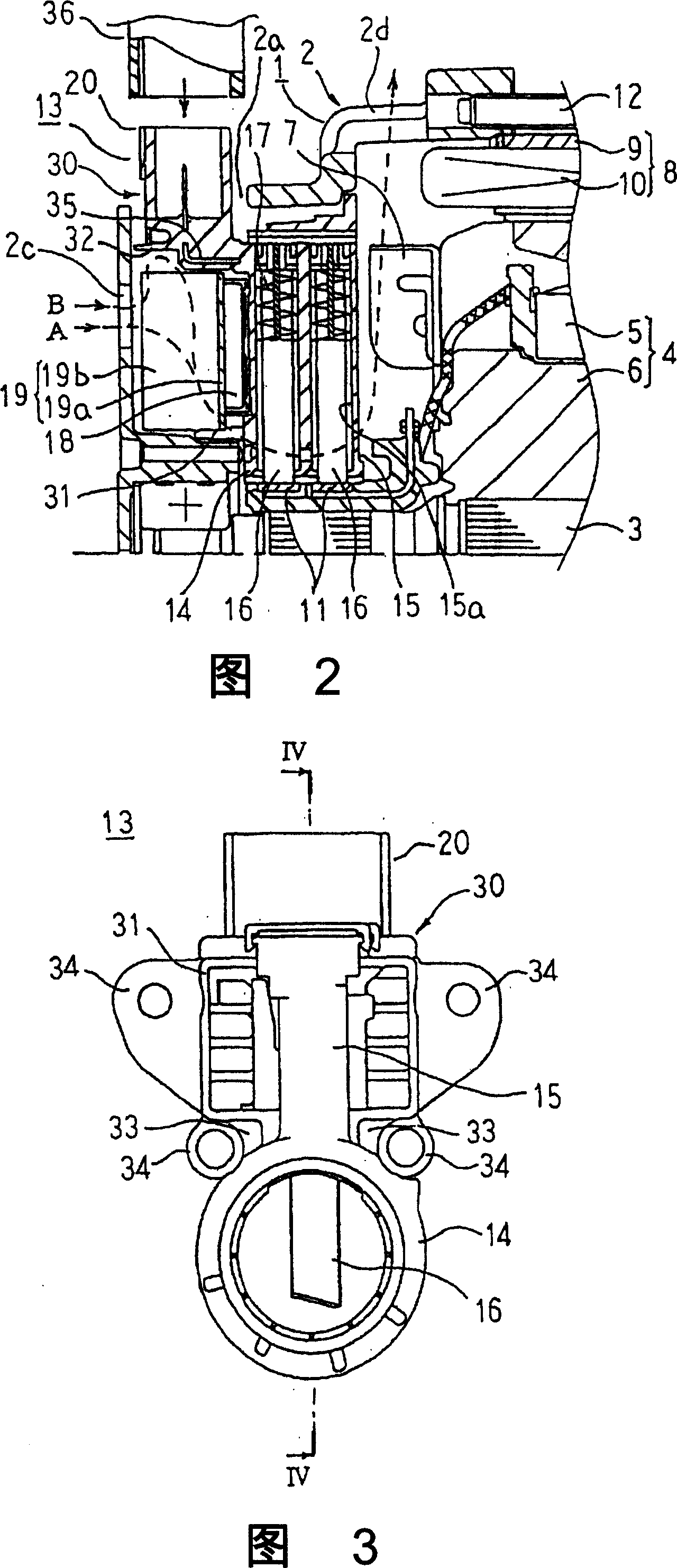
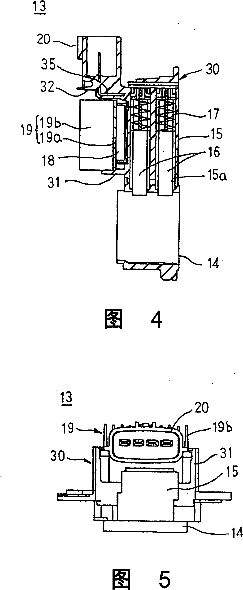
[0037] 1 is a view from the back of the vehicle alternator according to the embodiment of the present invention, FIG. 2 is a sectional view showing the main part of the vehicle alternator according to the embodiment of the present invention, The front view of the regulator assembly applicable to the vehicle alternator related to the embodiment of the present invention, Fig. 4 is a longitudinal sectional view of the IV-IV arrow in Fig. 3, Fig. 5 is a view from the side of the connector opening. Figure 6 and Figure 7 are diagrams for explaining the flow of cooling air in the vehicle alternator according to the embodiment of the present invention, respectively. A perspective view of the main parts.

[0038] In FIGS. 1 and 2 , the vehicle alternator has a housing 1 composed of a roughly bowl-shaped aluminum front cover (not shown) and a rear cover 2, supported by the housing 1 and capable of The rotating shaft 3 that rotates freely, the rotor 4 that is fixed on the rotating shaft...


PUM


Abstract

The present invention provides a vehicle alternator capable of suppressing deterioration of the cooling performance of a voltage regulator due to improvement of the cooling performance of the rectifier, suppressing temperature rises of the rectifier and the voltage regulator, and improving performance. The cooling air introduction guide part (32) ensures a predetermined gap with respect to the heat sink (19b) at the position facing the heat sink (19b) of the voltage regulator heat sink (19) of the connector (20), and along the heat dissipation The arrangement direction of the sheets (19b) extends. Then, an air suction hole (2c) is formed through the portion of the rear end cover (2) opposite to the heat sink (19) for the voltage regulator.

Description

technical field [0001] The invention relates to a vehicle alternator mounted on a vehicle, in particular to a structure for cooling a voltage regulator. Background technique [0002] In a conventional vehicle alternator, a rectifier unit is formed in a substantially C-shape, and a voltage regulator, a brush holder, and a connector are integrated to form a regulator unit. Furthermore, the voltage regulator and the brush holder are arranged so that they overlap in the axial direction of the rotation axis, and the connector is arranged on a plane that includes both the voltage regulator and the brush holder and is rotated in the circumferential direction by a predetermined distance from the two in a plane perpendicular to the rotation axis. The angled position is such that the opening faces in the radially outward direction. Then, the regulator unit is arranged in the space of the C-shaped opening of the rectifier unit. Therefore, the size of the heat sink of the rectifier is...

Claims


Application Information

Patent Timeline
Patent Type & Authority Applications(China)
IPC IPC(8): H02K9/00H02K9/06H02K11/00B60L50/13
CPCH02K5/225H02K5/141H02K9/06H02K9/28H05K7/20918H05K7/209H02K11/049H02K5/207H02K7/1815H02K2205/09
Inventor 伊藤慎一
Owner MITSUBISHI ELECTRIC CORP
Learn More