Plane multi-freedom altrasonic electric machine of single vibrator longtitude bend sandwich changer type

A technology of ultrasonic motors and transducers, which is applied in the direction of generators/motors, piezoelectric effect/electrostrictive or magnetostrictive motors, electrical components, etc. The output torque is small, the four driving feet are difficult to guarantee, etc., and the position and excitation combination are easy to determine, the vibration mode is simple, and the output force is large.

Inactive Publication Date: 2007-12-19
HARBIN INST OF TECH
View PDF0 Cites 23 Cited by
  • Summary
  • Abstract
  • Description
  • Claims
  • Application Information

AI Technical Summary

Problems solved by technology

[0003] The purpose of the present invention is to provide a single vibrator longitudinal bending sandwich transducer-type planar multi-degree-of-freedom ultrasonic motor, which can solve the problem that the three-degree-of-freedom planar ultrasonic motor has a small output torque, and it is difficult to ensure that the four driving feet are on one plane. The vibration mode is complex, the position and excitation combination of each ceramic piece are difficult to determine, and it is difficult to achieve series promotion

Method used


Image

  • Plane multi-freedom altrasonic electric machine of single vibrator longtitude bend sandwich changer type
  • Plane multi-freedom altrasonic electric machine of single vibrator longtitude bend sandwich changer type
  • Plane multi-freedom altrasonic electric machine of single vibrator longtitude bend sandwich changer type

Examples


specific Embodiment approach 1

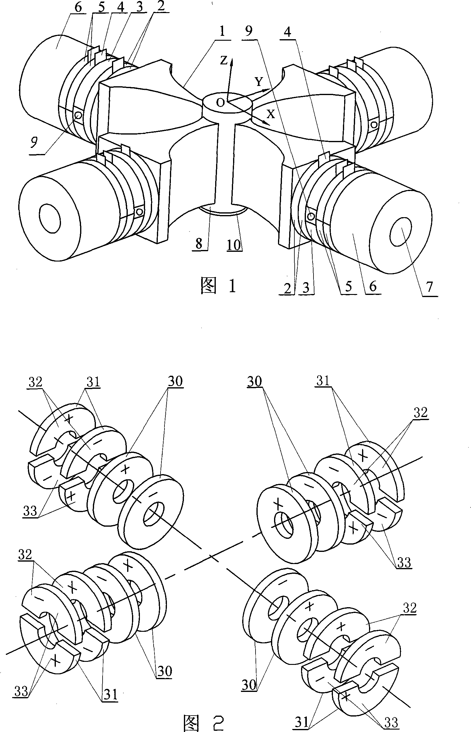
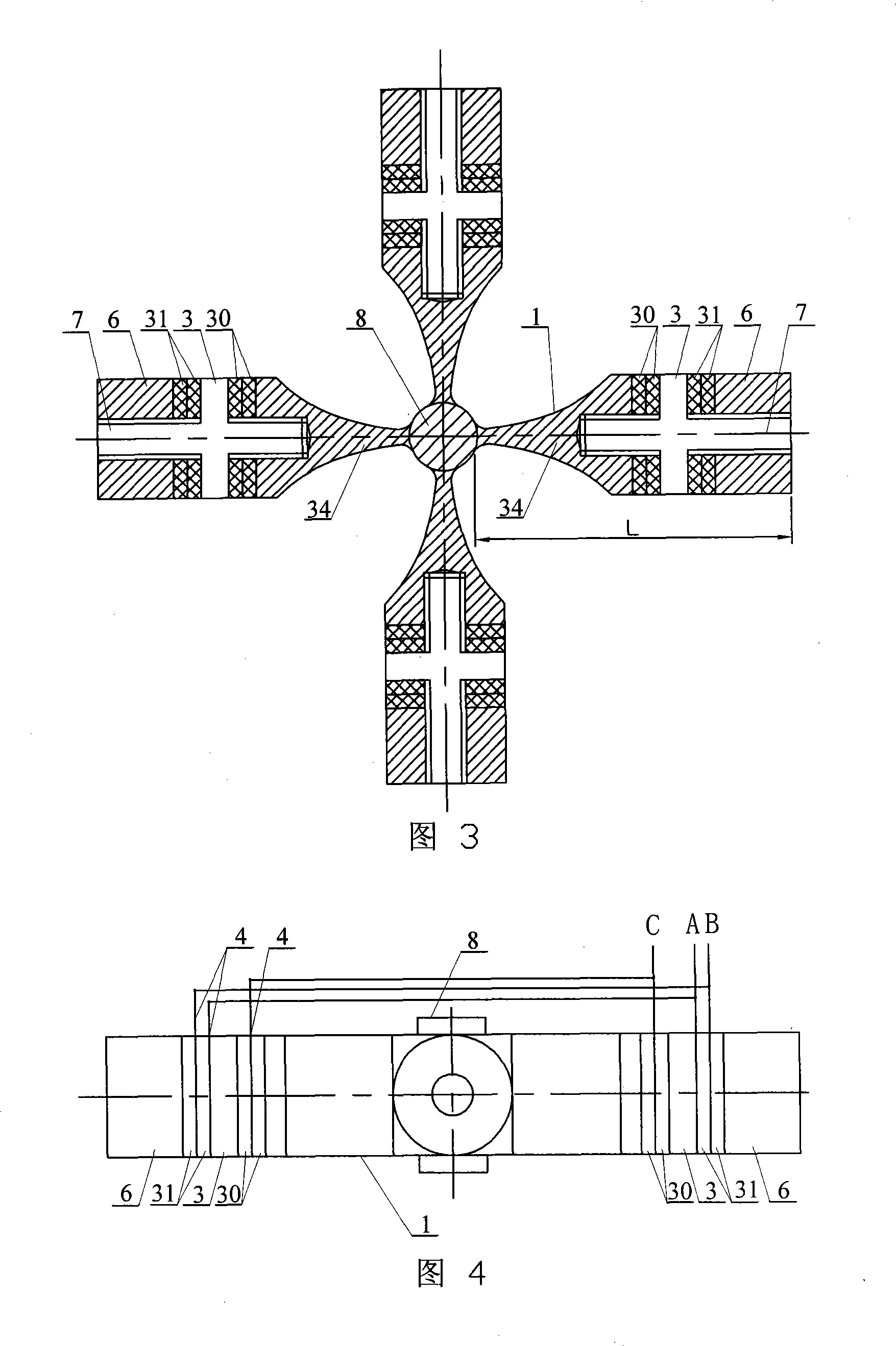
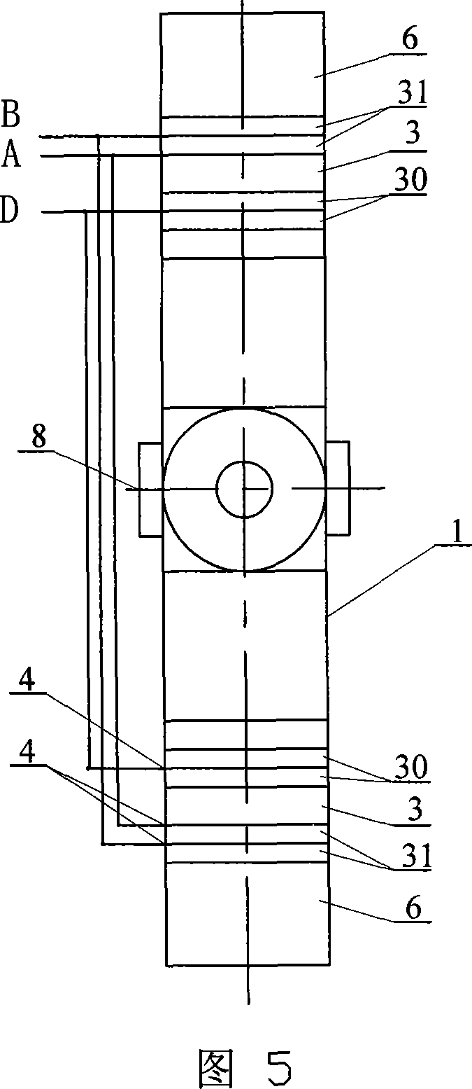
[0007] Specific embodiment 1: This embodiment will be described with reference to Figs. 1 to 5, this embodiment is composed of a single vibrator longitudinal bending sandwich transducer and a driving foot 8; the single vibrator longitudinal bending sandwich transducer is a cross orthogonal luffing The rod 1, the longitudinal vibration piezoelectric ceramic sheet group 2, the flange 3, the electrode copper sheet 4, the bending vibration piezoelectric ceramic sheet group 5, the end cover 6, and the stud 7; the vertical of the cross orthogonal horn 1 A stud 7 is provided on the axis, and the stud 7 is provided with a flange 3, the flange 3 is located at the nodal position of the longitudinal vibration of the single vibrator longitudinal bending sandwich transducer, and the flange 3 is orthogonal to the cross luff The stud 7 between the large end faces of the rod 1 is equipped with a longitudinal vibration piezoelectric ceramic sheet group 2, and the stud 7 between the flange 3 and th...

specific Embodiment approach 2

[0008] Specific embodiment 2: This embodiment will be described with reference to FIG. 3. The cross orthogonal horn 1 of this embodiment is composed of four horns 34 orthogonal in the same plane; the cross section of the horn 34 is Rectangular, the length L of the horn 34 is 1 / 4 or 1 / 2 the longitudinal vibration wavelength. With this arrangement, the horn 34 can reduce the loss of vibration energy on the large end face of the horn 34, play a role in accumulating vibration energy, increase the amplitude and vibration speed of the driving foot 8, and greatly improve the performance of the ultrasonic motor . The other components and connection relationships are the same as in the first embodiment.

specific Embodiment approach 3

[0009] Specific embodiment 3: This embodiment is described with reference to FIG. 1. In this embodiment, two small conical holes 9 are drilled where the longitudinal bending vibration nodes of the outer cylindrical surface of the flange 3 overlap. This setting is used as the clamping point of the ultrasonic motor pre-tightening force mechanism to apply pre-tightening force to generate driving friction, or to drive the load there. Choosing to drill two small conical holes 9 at this position has the least influence on the vibration shape of the single vibrator longitudinal-bending sandwich transducer and can reduce energy loss. The other components and connection relationships are the same as in the first embodiment.


PUM


Abstract

This invention relates to a supersonic motor, in which, a flange is set on a screw post, compressional vibration piezoelectric ceramic plate sets, bent vibration piezoelectric ceramic plate sets, pole copper plates and a cover are mounted on the post and fixed to become one unit with a cross orthogonal luff rod by the post, the polarization directions of two adjacent bent vibration piezoelectric ceramic sets are opposite and those of the two adjacent compressional piezoelectric ceramic sets are opposite, a drive foot is placed at the center of the luff rod and fixed to it.

Description

Technical field [0001] The invention relates to an ultrasonic motor and belongs to the technical field of piezoelectric ultrasonic motors. Background technique [0002] Planar multi-degree-of-freedom ultrasonic motor is a motor that uses ultrasonic vibration energy to generate driving force through friction. It directly drives the mover at low speed by friction coupling, which can realize linear or rotational motion with multiple degrees of freedom. It has a simple structure and is better than traditional In order to realize multi-degree-of-freedom movement, the electromagnetic motor needs to add complicated forms of variable speed, combination and decoupling mechanisms, and has low speed and large torque (thrust), no variable speed mechanism, no electromagnetic interference, fast response speed and power-off self-locking, etc. Advantages, as a piezoelectric driver has a very wide range of applications. In the past, the research of multi-degree-of-freedom planar motion mechanism ...

Claims


Application Information

Patent Timeline
Patent Type & Authority Applications(China)
IPC IPC(8): H02N2/12
Inventor 陈维山赵学涛刘军考谢涛
Owner HARBIN INST OF TECH
Why Eureka
Try Eureka