Internal cooling, heating type apparatus for dehumidifying and regenerating solution, and dehumidifying and regenerating method

A solution dehumidification and regeneration device technology, applied in heating methods, separation methods, chemical instruments and methods, etc., can solve the problems of poor dehumidification/regeneration effect, decrease, dehumidification/regeneration solution temperature rise, etc., to achieve high efficiency and performance. stable effect

Inactive Publication Date: 2007-12-26
SOUTHEAST UNIV
View PDF0 Cites 19 Cited by
  • Summary
  • Abstract
  • Description
  • Claims
  • Application Information

AI Technical Summary

Problems solved by technology

[0004] Technical problem: the purpose of the present invention is to overcome the deficiencies in the prior art, and propose an internal cooling-internal heating type solution dehumidification-regeneration device and a dehumidification-regeneration method, which are mainly used to overcome the existing solution dehumidification/regenerator (regeneration devi...

Method used


Image

  • Internal cooling, heating type apparatus for dehumidifying and regenerating solution, and dehumidifying and regenerating method

Examples


Embodiment 1

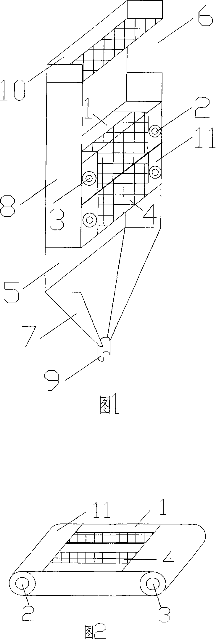
[0018] Example 1: LiCl solution regeneration process. Dehumidification and regeneration unit 11 has a channel height of 1m and a width of 0.3m. A plate-fin heat exchanger is selected as the core of the regenerator, and the plate-fin expansion coefficient is 5. When the cold / heat medium channel has no internal heat When the working fluid is flowing, the regenerator is an adiabatic regenerator. The dehumidification regeneration method is divided into the flow of the solution, the flow of the air, and the flow of the cold / heat medium, among which,

[0019] 1) The process of the solution: the solution first enters the liquid distribution tank 10, which makes the solution uniformly distributed and then falls to the heat and mass exchange bed 4 due to the action of gravity, forming a falling film on the surface of the heat and mass exchange bed 4 of the dehumidification regeneration unit 11, and in the The surface of the heat-mass exchange bed 4 exchanges heat and mass with the coun...

Embodiment 2

[0023] Example 2: LiCl solution dehumidification process. The structure of the internal cooling type dehumidification device is similar to the structure of the regeneration device mentioned above. The channel flow rate of the wet air unit is 0.0098kg / s, the temperature is 25.0°C, and the moisture content is 11.5g / kg dry air; The mass flow rate of the dehumidification solution is 0.016kg / s, the temperature is 27°C, the mass percentage concentration is 40.0%, the mass flow rate of the internal cooling working medium is 0.04kg / s, and the temperature is 25°C. In the adiabatic dehumidifier, both the solution temperature and the air temperature increase gradually, the solution temperature rises from 27°C to 28.7°C, and the air temperature rises from 25°C to 26.2°C. In the internal cooling type dehumidification device, the solution temperature gradually decreases due to the internal cooling water, and the outlet temperature is only 26.1°C, and the air temperature has a small increase,...


PUM


Abstract

The invention relates to a bore surface cooling-internal heat type solution dehumidify-regeneration method, in the interior of dehumidifies/regeneration unit, the cold/ heat carrier channel and the caloric exchange bed interaction are arranged. In the solution dehumidifies/regenerative process, the cold/heat carrier incessancy carries the heat exchange with the solution, and takes away the heat which is produced in the dehumidify process to keep the temperature of the solution in the dehumidify/regenerative process in the low/high condition, in the set, the receiving tank (7) is located below the rectangular outer covering and the heat insulating layer (8) and connects, the solution exports (9) is located below the receiving tank (7) and connects, the cloth fluid bath (10) and the dehumidifies regeneration unit (11) separately is located at the upside and middle of rectangular outer covering and heat insulating layer, the deficiency wind exports (6) is located at the rectangular outer covering and one side of the heat insulating layer between the cloth fluid bath (10) and the dehumidify/regeneration unit, the new atmosphere imports (5) is located at the rectangular outer covering and another side of the heat insulating layer between the dehumidifies/regeneration unit and receiving tank.

Description

technical field [0001] The invention relates to a solution dehumidification-regeneration device and a dehumidification-regeneration method, in particular to an internal cooling-internal heating type solution dehumidification-regeneration device. Background technique [0002] The solution dehumidification / regeneration device is to allow air and solution to exchange heat and mass on the heat and mass exchange bed to achieve the purpose of dehumidification / regeneration. The mechanism of solution dehumidification and regeneration is the same, and the driving force of mass transfer is the difference between the partial pressure of water vapor on the surface of the solution and the partial pressure of water vapor in the air. The difference is the direction of mass transfer. During the dehumidification process, the water vapor in the air is absorbed by the dehumidification solution, and the solution absorbs moisture and condenses heat. In the regeneration process, the water in th...

Claims


Application Information

Patent Timeline
IPC IPC(8): B01D53/26F24F3/14
Inventor 张小松王庚殷勇高
Owner SOUTHEAST UNIV
Why Eureka
Try Eureka