
Electrical percussive tool

An impact tool, electric technology, applied in the direction of lightweight impact tools, striking tools, manufacturing tools, etc., can solve the problems of complex manufacturing process, bulky, expensive and so on

Inactive Publication Date: 2007-12-26
孙玉坤
View PDF0 Cites 16 Cited by
  • Summary
  • Abstract
  • Description
  • Claims
  • Application Information

AI Technical Summary

Problems solved by technology

However, due to the complex manufacturing process of many existing marking machines, lasers or air compressors are required as driving sources, resulting in bulky size and high price, so it is difficult to popularize them in a large area among ordinary users.

Method used


Image

  • Electrical percussive tool
  • Electrical percussive tool

Examples


Embodiment Construction

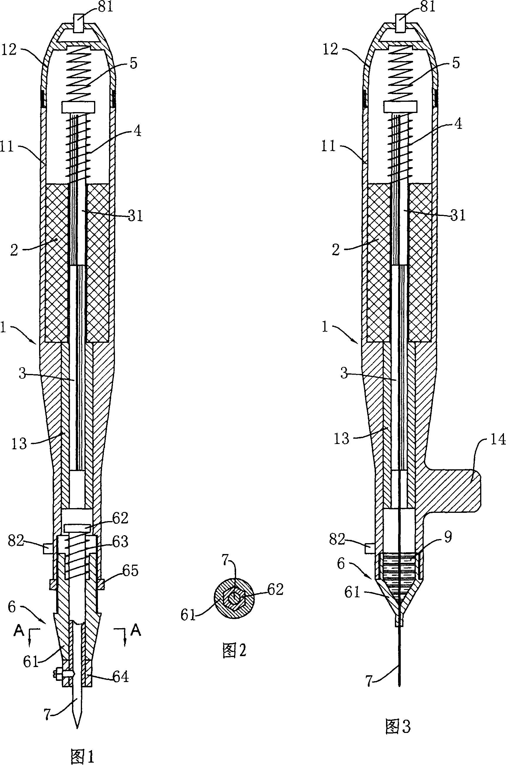
[0022] Fig. 1 shows a kind of electric percussion tool mainly used for engraving operation, and it comprises the housing 1 of pen shape, and housing 1 has an open end and a closed end 12, and the closed end 12 of housing 1 is connected with The body part 11 of the housing is screwed. The housing 1 is designed in the shape of a pen, which is not only attractive, but also convenient for handheld use. A power device for driving the tool to move linearly is installed in the housing 1, which is the core part of the impact tool. The open end of the housing 1 is installed with a tool holder device 6 for clamping a tool 7 .

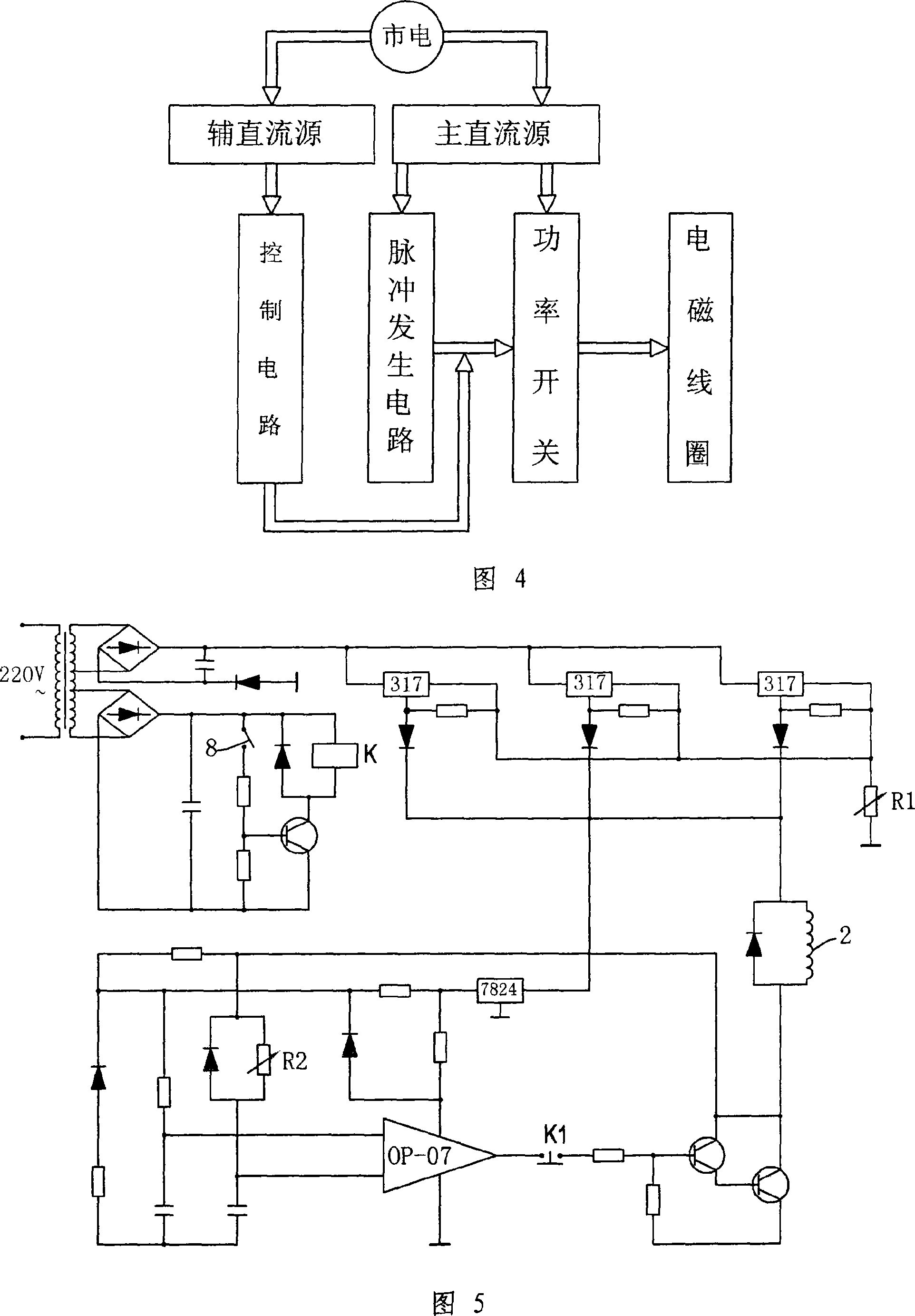
[0023] The power device includes an electromagnetic coil 2 fixed inside the housing, the electromagnetic coil is connected to the pulse power supply device; the impact rod 3 can be moved axially along the guide part 13 located in the housing, and the impact rod 3 can move axially Pass through and both ends protrude from the inner cavity of the electromagnetic c...


PUM


Abstract

The invention discloses an electric drive impact tool. The main technical feature includes: electromagnetic coil connecting to impulse power supply is set in the case; impact bar passing through the cavity of electromagnetic coil; iron core section, which is located at the opening part moving toward after the impact bar having magnetic force, is set in the impact bar; under free state, the first elastic component and the second elastic component constraining the impact bar on the certain original location. The linear movement of impact bar could be generated by magnetic force. Thus, it is quiet, and reliable, and the volume is sharply decreased. It could be widely used in the fields of carving, magnetism carving, hammering, etc.

Description

technical field [0001] The invention relates to the technical field of electric impact tools, in particular to an electric impact tool used for operations such as tattooing, engraving, woodworking chisel, magnetic engraving, hammering or marking. Background technique [0002] Known tattooing tools, such as eyebrow tattooing machine or tattoo machine, its principle is to penetrate the epidermis of human skin through tattooing needles, and deposit the pigments on the tattooing needles into the epidermis to form various patterns. In the process, the tattooing needle makes a linear reciprocating motion, and sometimes it is necessary to adjust the frequency and strength of the tattooing needle. The power in the known structure is provided by the motor, and its rotary motion can be converted into a linear motion through a series of transmission devices. In this way, the eyebrow tattoo machine or tattoo machine is not only noisy, but also has low transmission efficiency and relativ...

Claims


Application Information

Patent Timeline
Patent Type & Authority Applications(China)
IPC IPC(8): B25D13/00B25D17/08
Inventor 孙玉坤
Owner 孙玉坤
Learn More