Method for anti-floating of underground building

A technology for underground buildings and scuppers, applied in construction, protection devices, infrastructure engineering, etc., can solve the problems of high cost, great difficulty, long construction period, etc. Effect

Active Publication Date: 2008-01-02
袁奕
View PDF3 Cites 19 Cited by
  • Summary
  • Abstract
  • Description
  • Claims
  • Application Information

AI Technical Summary

Problems solved by technology

The cost of the above three methods is very high, and the construction period of the latter two methods is also long, especially when the underground buildings have been floated, it is more difficult to use the above methods to remedy

Method used


Image

  • Method for anti-floating of underground building

Examples


Embodiment 1

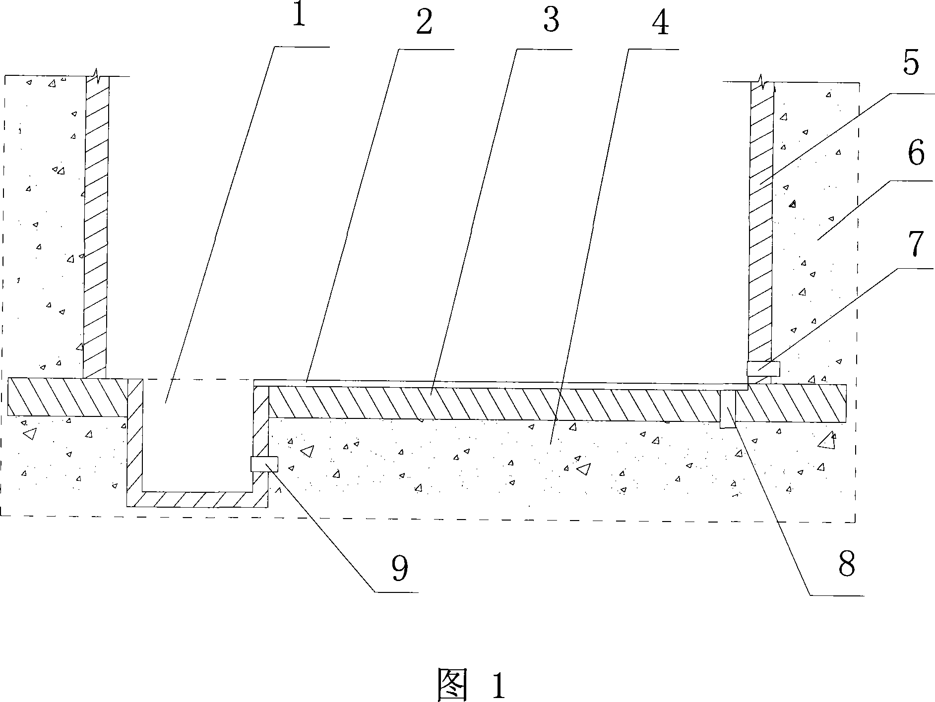
[0037] A method for anti-floating of underground buildings, 1) first water discharge hole 7 is set at the bottom of underground building outer wall 5 (new construction is to reserve the first water discharge hole 7, and built project is to excavate the first water discharge hole 7), the diameter of the first drain hole 7 is 80-120mm, the first drain hole 7 is provided with a replaceable filter device, the replaceable filter device includes a graded sand filter layer and an indoor side Sealing filter device on the hole (such as steel wool, polyolefin foam, etc.);

[0038] One end of the first weep hole 7 communicates with the indoor drainage groove 2 of the underground building (if the original drainage groove is inappropriate, a new drainage groove can be added), and the other end of the first weep hole 7 is located outside the underground building Outside the wall 5 (groundwater in the outdoor filling 6 flows into the drainage ditch 2 through the first weep hole 7);

[0039]...

Embodiment 2

[0044] A method for anti-floating of underground buildings, 1) second scupper holes 8 are set on the bottom plate of underground buildings ), the diameter of the second drain hole 8 is 80-120mm, the second drain hole 8 is provided with a replaceable filter device, the replaceable filter device includes a graded sandstone filter layer and an indoor side hole Sealed filter device (such as steel ball, polyolefin foam, etc.);

[0045] The upper end of the second drain hole 8 communicates with the indoor drainage groove 2 of the underground building (as the original drainage groove position is improper, a new drainage groove can be added), and the lower end of the second drain hole 8 is located at the base plate of the underground building 3 Down (groundwater in the base soil 4 flows into the drainage ditch 2 through the second weep hole 8);

[0046] The diameter and quantity of the second weep hole 8 are calculated and determined according to the specific conditions of the projec...

Embodiment 3

[0050] As shown in Figure 1, a kind of anti-floating method of underground building, 1) the first scoop hole 7 is set in the bottom of underground building outer wall 5 (new project is to reserve the first scoop hole 7, built project It is to excavate the first weep hole 7), the diameter of the first weep hole 7 is 80-120mm, the first weep hole 7 is provided with a replaceable filter device, the replaceable filter device includes graded sand The stone filter layer and the sealing filter device (such as steel ball, polyolefin foam, etc.) on the indoor side hole; one end of the first weep hole 7 communicates with the indoor drainage groove 2 of the underground building (if the original drainage groove is not properly located , can add drainage ditch), the other end of the first weep hole 7 is located outside the exterior wall 5 of the underground building (the groundwater in the outdoor filling soil 6 flows into the drainage ditch 2 through the first weep hole 7);

[0051]The se...


PUM


Abstract

The invention discloses a method of underground structure against floating, which is characterized by the following: 1)adopting the following methods; a)arranging first drained hole (7)on lower of underground structure outside wall (5); b)arranging second drained hole (8)on underground structure bottom plate (3); c)arranging the first drained hole (7)on the lower of the underground structure outside wall (5); arranging the second drained hole on the underground structure bottom plate (3); 2)arranging drained tank (2)on the inner of the underground structure exterior wall; communicating with collecting well (1)in the underground structure; 3)discharging the water in the collecting well out of the underground structure; arranging third drained hole (9)on the wall of the collecting well (1); proceeding pressure poured cement paste under the underground structure bottom plate (3); change-filling backfill soil (6)of the underground structure outside wall (5)in the zone with big creep quantity. This invention possesses the advantages of simple and firm.

Description

technical field [0001] The invention relates to a method for anti-floating of an underground structure. Background technique [0002] When the soil covering weight of underground buildings is not enough, under the action of surface water and groundwater, floating phenomenon often occurs. When the underground structure floats, it will be accompanied by the cracking and damage of the structural bottom plate and column, which is difficult and costly to remedy. [0003] With the rapid development of my country's economy, a large number of urban underground garages have emerged. These underground garages are often single-storey basements, and the weight of the structure itself is difficult to balance the buoyancy of water. Recently, accidents that cause single-storey basements to float have occurred frequently. [0004] At present, there are three ways to prevent underground buildings from floating: one is to increase the weight of the structure itself, such as thickening the ro...

Claims


Application Information

Patent Timeline
Patent Type & Authority Applications(China)
IPC IPC(8): E02D31/02E02D31/12
Inventor 袁奕
Owner 袁奕
Why Eureka
Try Eureka