Liquid crystal display device and driving method

一种液晶显示装置、源极驱动的技术,应用在静态指示器、非线性光学、仪器等方向,能够解决电路规模增大等问题

Inactive Publication Date: 2008-01-02
MITSUBISHI ELECTRIC CORP
View PDF2 Cites 15 Cited by
  • Summary
  • Abstract
  • Description
  • Claims
  • Application Information

AI Technical Summary

Problems solved by technology

However, in Patent Document 2, since another charging circuit is required, the circuit scale increases

Method used


Image

  • Liquid crystal display device and driving method
  • Liquid crystal display device and driving method
  • Liquid crystal display device and driving method

Examples


Embodiment 1

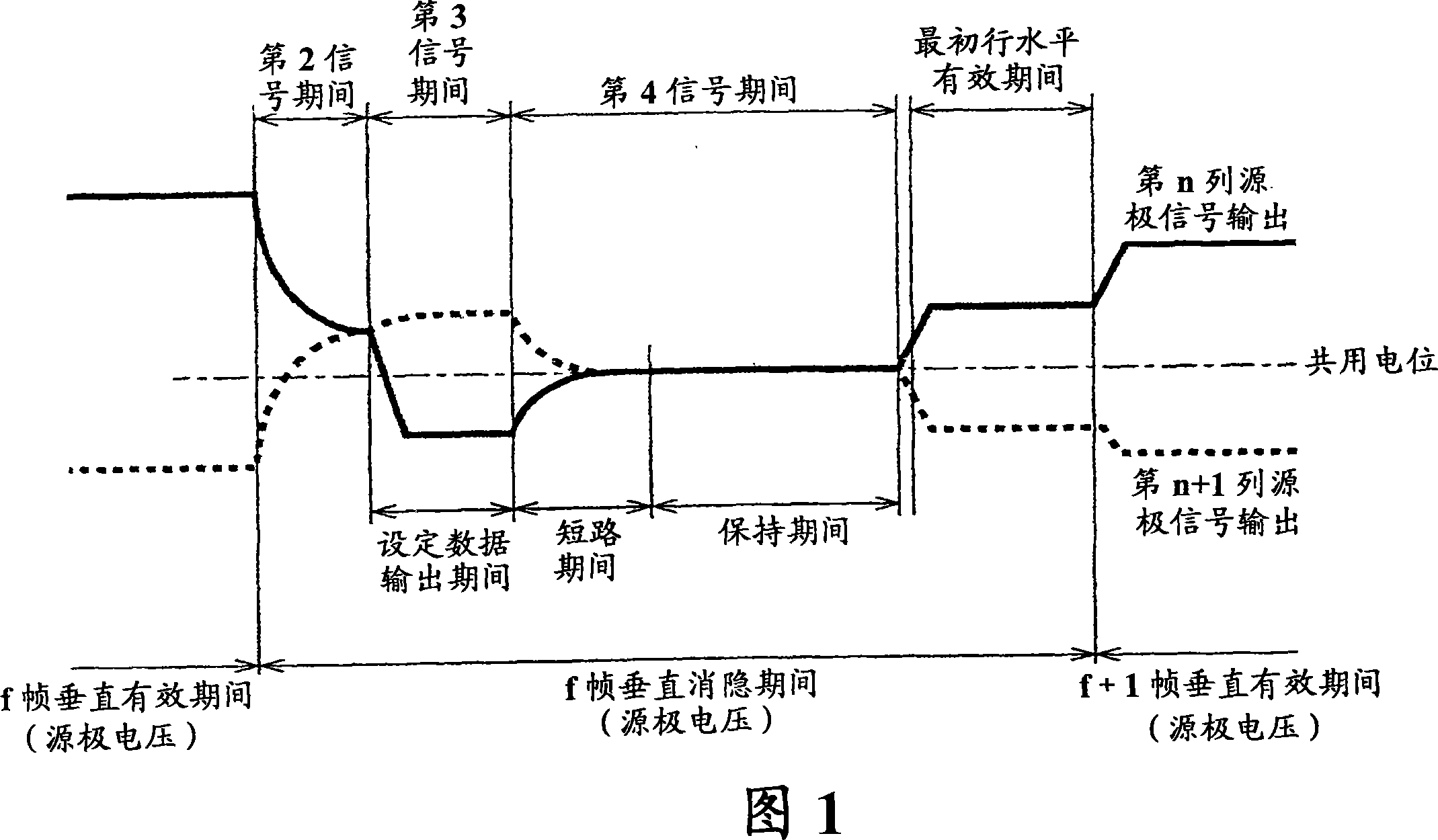
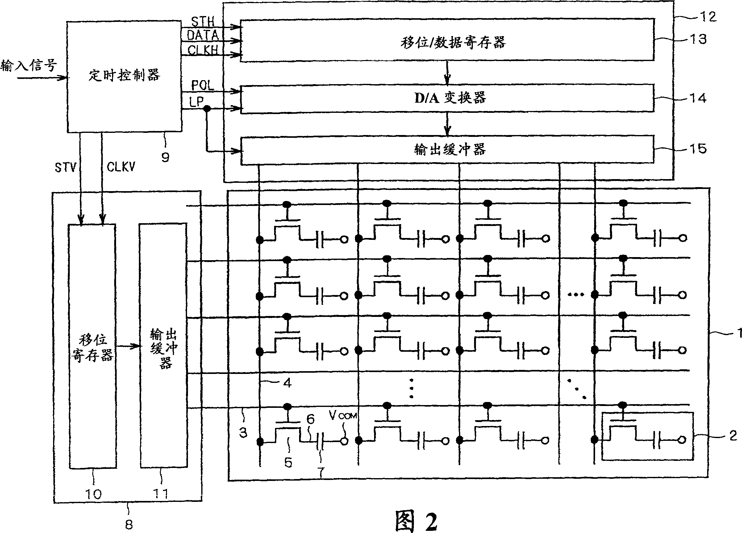
[0054] FIG. 1 shows changes in the source line potential of the liquid crystal display device of this embodiment. FIG. 2 shows a block diagram of the liquid crystal display device of this embodiment. First, the structure of the liquid crystal display device of this embodiment will be described with reference to FIG. 2 . Furthermore, the liquid crystal display device of this embodiment can adopt the structure of a common active matrix TFT liquid crystal display device.

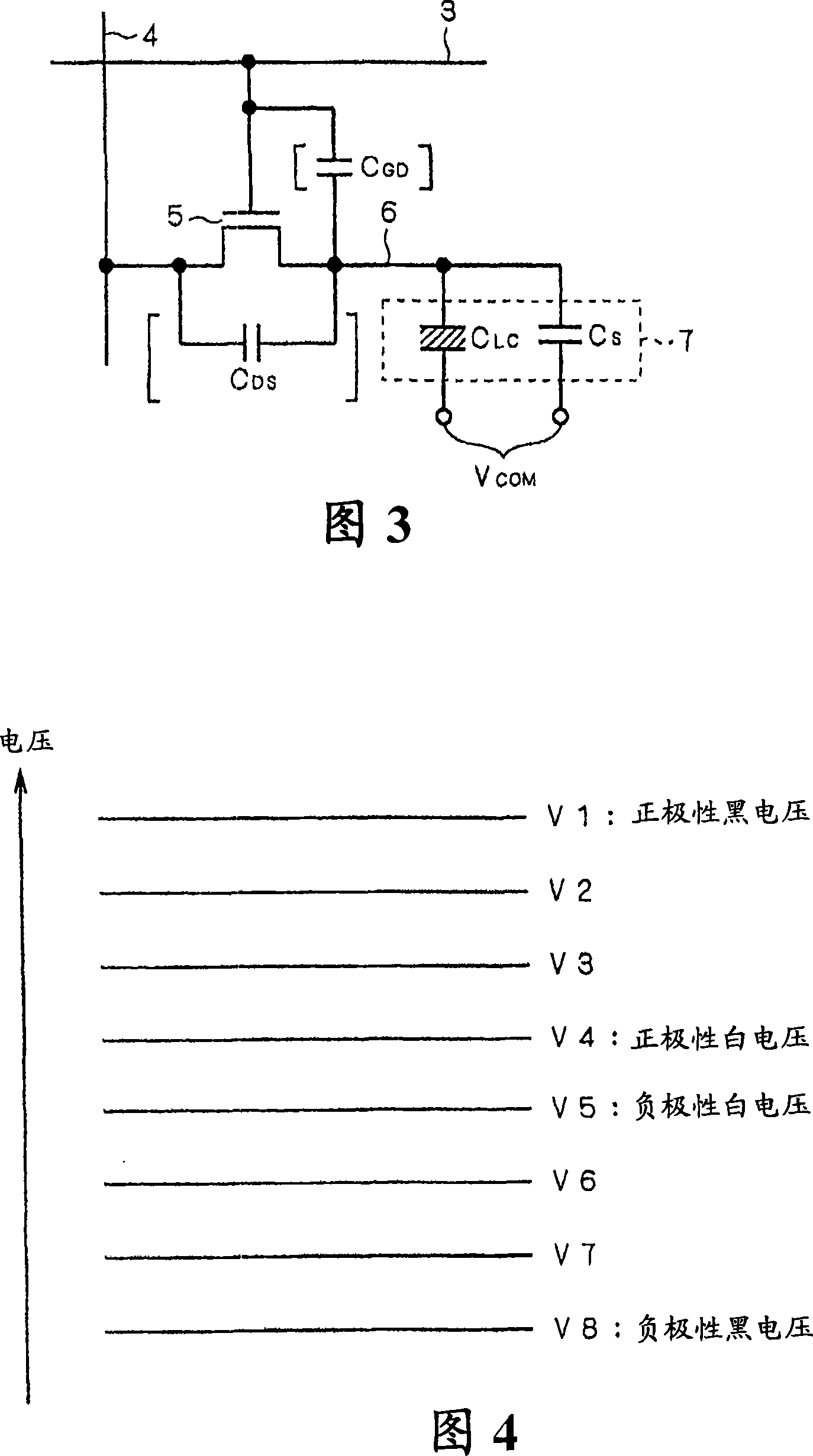
[0055] First, in the liquid crystal display device of FIG. 2 , pixels 2 are arranged in a matrix on a translucent substrate 1 , and gate lines 3 and source lines 4 are arranged to surround the pixels 2 . Furthermore, a thin film transistor (TFT5) which is an active element is provided at the intersection of the gate line 3 and the source line 4, and the drain 6 of the TFT5 is connected to the pixel electrode. In addition, a counter substrate (not shown) is provided at a position facing the substrate 1 on whic...

Embodiment 2

[0107] In a general liquid crystal display device, a gate driver is provided on one side of the gate line to drive the gate line. Therefore, the waveform of the gate signal is steep near the input end of the gate line, and the waveform of the gate signal becomes gentler due to the resistance and parasitic capacitance of the gate line as it moves away from the input end. Even in a liquid crystal display device in which gate drivers are provided on both sides of the gate line and driven from both sides of the gate line, the waveform of the gate signal near the center of the gate line is gentler than that near the input end.

[0108] In the liquid crystal display device, since the waveform of the gate signal is gentle, there is a difference in the gate signal along the horizontal direction (gate line direction) of the liquid crystal display device. Due to the difference of the gate signal, the source potential feed-through voltage (ΔV CGD ) make a difference. Specifically, when...


PUM


Abstract

A liquid crystal display device includes pixels, gate lines and source lines, active elements, a gate driver circuit, a source driver circuit, and a timing controller circuit. The source driver circuit conducts a prescribed operation of supplying the source signals of positive polarity and negative polarity having a prescribed voltage to the source lines during a vertical blanking interval, and electrically cutting the source lines off after the supply of the source signals while establishing a short circuit between adjoining source lines supplied with the source signals of opposite polarities, thereby causing the source lines to hold a prescribed DC voltage value.

Description

technical field [0001] The present invention relates to a liquid crystal display device and a driving method thereof, in particular to a liquid crystal display device provided with active elements and a driving method thereof. Background technique [0002] The structure and operating principle of a general active matrix type TFT (Thin Film Transistor) liquid crystal display device (hereinafter, simply referred to as a liquid crystal display device) will be described. First, in a liquid crystal display device, pixels are arranged in a matrix on a light-transmitting substrate, and gate lines and source lines are arranged so as to surround the pixels. Furthermore, a thin film transistor (TFT) which is an active element is provided at the intersection of the gate line and the source line, and the drain of the TFT is connected to the pixel. Furthermore, a counter substrate is provided at a position facing the array substrate on which the pixels are formed, and the liquid crystal...

Claims


Application Information

Patent Timeline
Patent Type & Authority Applications(China)
IPC IPC(8): G02F1/1362G09G3/36
CPCG09G2320/0247G09G2310/061G09G2320/0214G09G2320/0204G09G2330/021G09G2320/0219G09G3/3614G09G2330/023G09G2320/0223G09G3/3688G09G2310/0248G09G3/36G02F1/133G09G3/20
Inventor 石口和博
Owner MITSUBISHI ELECTRIC CORP
Why Eureka
Try Eureka