Thermal spraying nozzle device and thermal spraying equipment

A nozzle device and nozzle technology, which can be used in spray devices, liquid spray devices, fusion spraying and other directions, can solve the problems of not designing nozzles, unable to obtain high-density coating or high-density stacking, etc.

Inactive Publication Date: 2008-01-02
KOBE STEEL LTD
View PDF2 Cites 13 Cited by
  • Summary
  • Abstract
  • Description
  • Claims
  • Application Information

AI Technical Summary

Problems solved by technology

[0013] Also, the latter spraying device atomizes at supersonic speed, but does not design a nozzle to accelerate particles, so high-density coating or high-density accumulation cannot be obtained to the extent that HIP (hot isostatic pressing) can be omitted.

Method used


Image

  • Thermal spraying nozzle device and thermal spraying equipment
  • Thermal spraying nozzle device and thermal spraying equipment
  • Thermal spraying nozzle device and thermal spraying equipment

Examples


Embodiment Construction

[0059] Hereinafter, the present invention will be described in detail based on the illustrated embodiments.

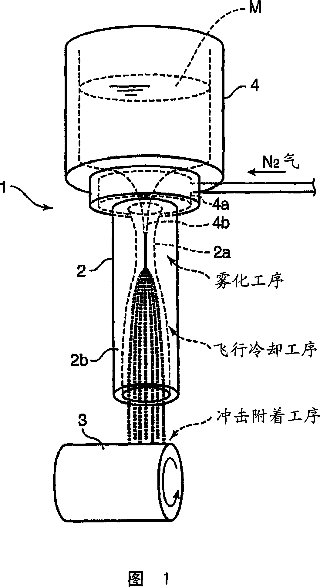
[0060] Fig. 1 shows the basic structure of the sputtering nozzle device of the present invention.

[0061] 1. The principle of spraying nozzle device

[0062] The spraying nozzle device 1 shown in the figure supplies molten metal M directly into a supersonic nozzle (hereinafter referred to as a nozzle) 2 .

[0063] On the one hand, what flows through the nozzle 2 is a supersonic airflow, and on the other hand, the molten metal supplied to the nozzle 2 is a low-speed flow, so that a shear force acts between the two, and the surface tension of the molten metal acts, by This performs atomization (atomization) of the molten metal downstream of the slit portion 2 a of the nozzle 2 .

[0064] The atomized metal particles (hereinafter simply referred to as particles) are accelerated and rapidly cooled in the nozzle 2 to solidify. That is, in the spraying nozzle device 1 of...


PUM

PropertyMeasurementUnit
diameteraaaaaaaaaa

Abstract

To provide a thermal spraying nozzle device and thermal spraying equipment on which a thermal spraying material can be supplied constantly and filming or deposition state can be controlled. In a thermal spraying nozzle device for forming an ultrahigh speed gas stream by introducing carrier gas to the inlet side of a nozzle and then atomizing a thermal spraying material by that gas stream and discharging the atomized thermal spraying material, a storage section (4) for storing molten metal as the thermal spraying material is connected to the inlet side end of the nozzle (2) through a communication passage, the nozzle has a throat portion (2a) for accelerating the introduced carrier gas to supersonic velocity, and a diameter-expanded channel portion (2b) formed on the downstream side of the throat portion toward the outlet direction. The thermal spraying nozzle is characterized in that the metal particles atomized by the supersonic gas stream are cooled down to solidification or semi-solidification state at the diameter-expanded channel portion.

Description

technical field [0001] The present invention relates to a thermal spraying nozzle device and a thermal spraying device which atomize a thermal spraying material using gas and hit a base material to form a film or a deposited layer. Background technique [0002] Conventionally, thermal spraying is known as a technique for forming a coating by heating molten or semi-molten fine particles on the surface of a substrate at high speed by heating the coating material. [0003] In this spraying treatment, since the substrate and the coating are physically bonded, a coating can be formed on any material as long as it is a molten material, and the formed coating can achieve wear resistance, corrosion resistance, heat insulation, etc. Various conditions necessary for surface treatment such as resistance, so it is widely used in various fields. [0004] Among them, cold spraying does not melt or vaporize the spraying material, but makes it collide with the inert gas on the substrate in...

Claims


Application Information

Patent Timeline
Patent Type & Authority Applications(China)
IPC IPC(8): B05B7/04C23C4/00
CPCB05B7/14B05B7/168C23C4/121B05B7/1463C23C4/123
Inventor 织田刚三宅俊也畠英雄
Owner KOBE STEEL LTD
Why Eureka
Try Eureka