
Apparatus and respective method for communicating with a transponder and system for communicating

a transponder and communication method technology, applied in the direction of synchronisation signal speed/phase control, instruments, electromagnetic radiation sensing, etc., can solve the problems of no individual energy resources, rfid transponders only have little energy, and can not influence or change transmitted data. , to achieve the effect of constant energy supply

Active Publication Date: 2020-03-31
FRAUNHOFER GESELLSCHAFT ZUR FOERDERUNG DER ANGEWANDTEN FORSCHUNG EV
View PDF22 Cites 0 Cited by
  • Summary
  • Abstract
  • Description
  • Claims
  • Application Information

AI Technical Summary

Benefits of technology

This patent describes various configurations for a transmit apparatus that can efficiently and accurately modulate signals for transmission. The technical effects include improved demodulation of amplitude-modulated signals, reduced computing power for phase modulation, and constant energy supply for RFID transponder through repetitive emission of the transmit signal. Additionally, the patent discusses the ability of the transmit apparatus to communicate with multiple receivers and transponders at the same time, resulting in a more complex and selective signal transmission.

Problems solved by technology

If data are transmitted in a contactless and in particular in a wireless manner, e.g., via electromagnetic waves, interferences that can possibly even influence or change the transmitted data can be coupled in by noise or by crosstalk of other signals.
If the received data deviate from the checksum, obviously, an error has occurred during transmission.
Generally, these RFID transponders have only little energy or no individual energy resources at all.
However, the increased data volume is disadvantageous, in particular in the example of the RFID transponders having limited energy resources.
If, for example, the receive signal would have to carry a signal portion of the transmit signal, but differences as regards to shape, frequency or wave form in general occur (e.g., due to interruptions), this means that the signal from the transponder to the apparatus has been damaged and that the data signal extracted from the receive signal can be erroneous.
This reduces computing power, for example compared to frequency modulation.

Method used


Image

  • Apparatus and respective method for communicating with a transponder and system for communicating
  • Apparatus and respective method for communicating with a transponder and system for communicating

Examples


Embodiment Construction

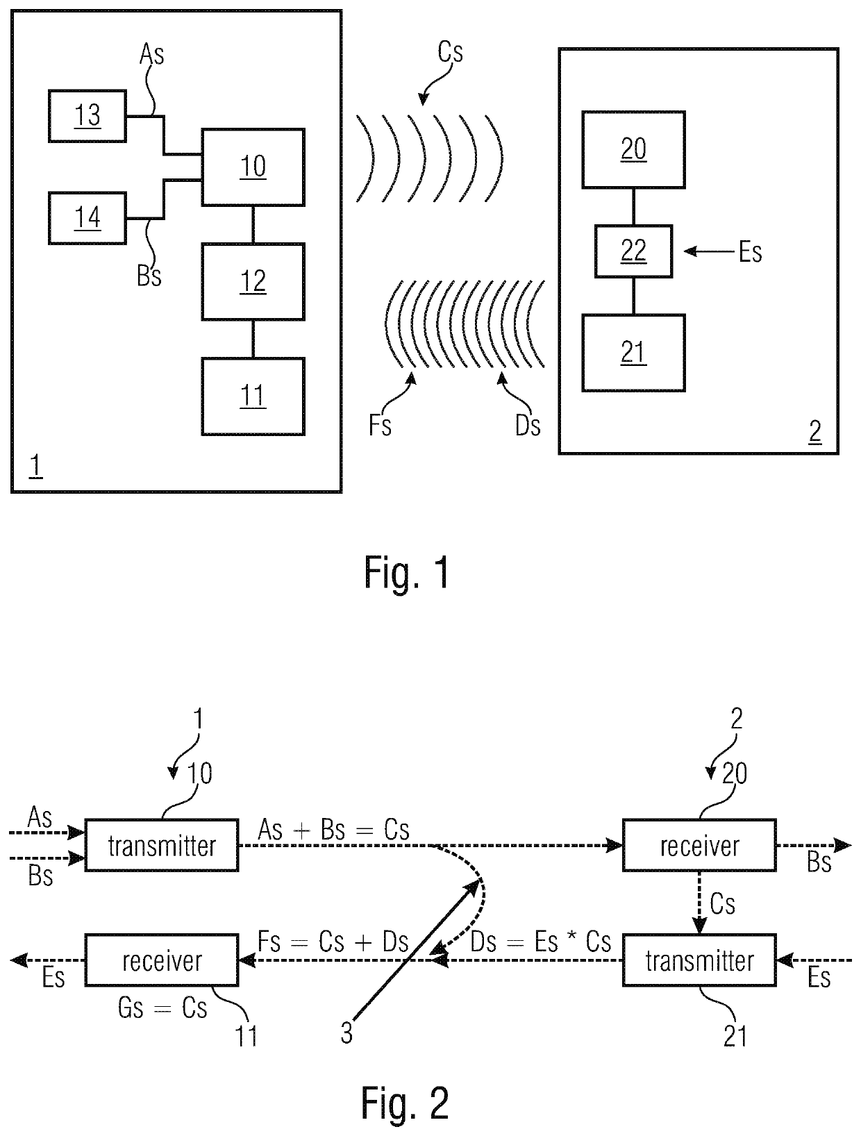
[0068]The apparatus 1 for wireless and radio-based communication with a transponder and the transponder 2 form a system for communication between the apparatus 1 and the transponder 2.

[0069]The apparatus 1 comprises a transmit apparatus 10 for emitting a transmit signal Cs in the direction of the transponder 2. For the transmit signal Cs, the transmit apparatus 10 is connected to two different signal sources 13, 14 each providing a first signal portion As and a second signal portion Bs, respectively. In an exemplary configuration, the second signal portion Bs allows the transmission of data from the apparatus 1—alternative terms are, for example, depending on the configuration, base station or reader—to the transponder 2. In a different configuration, no data are transmitted, such that, for example, no multi-part transmit signal Cs exists.

[0070]Thus, the transmit signal Cs comprises two different signal portions As, Bs, such that the transmit signal Cs can also be written as the sum...


PUM


Abstract

The invention relates to an apparatus for communicating with a transponder. The apparatus includes a transmit apparatus, a receive apparatus and an evaluation apparatus. The transmit apparatus transmits a transmit signal to the transponder. Based on a signal emitted by the transponder, the receive apparatus receives a receive signal. Based on the transmit signal and / or a signal portion, the evaluation apparatus evaluates the receive signal with respect to data errors. Further, the invention relates to a respective method as well as to a system for communicating.

Description

CROSS-REFERENCE TO RELATED APPLICATIONS[0001]This application claims priority from German Patent Application No. 10 2016 221 660.0, which was filed on Nov. 4, 2016, and is incorporated herein in its entirety by reference.[0002]The invention relates to an apparatus for communicating with a transponder as well as to a system for communicating. Further, the invention relates to a method for communicating with a transponder.BACKGROUND OF THE INVENTION[0003]If data are transmitted in a contactless and in particular in a wireless manner, e.g., via electromagnetic waves, interferences that can possibly even influence or change the transmitted data can be coupled in by noise or by crosstalk of other signals. For ensuring secure data transmission, it is known to transmit the data in a redundant manner, for example by transmitting, e.g., checksums together with the actual data. If the received data deviate from the checksum, obviously, an error has occurred during transmission. Here, the sign...

Claims


Application Information

Patent Timeline
Patent Type & Authority Patents(United States)
IPC IPC(8): G06K7/10G06K7/00H04L27/227G01S13/76H04L7/04
CPCG06K7/10118G06K7/10346H04L27/2273G06K7/0008H04L7/042G01S13/765
Inventor SCHMIDT, PHILIPVOM BOEGEL, GERDMEYER, FREDERIC
Owner FRAUNHOFER GESELLSCHAFT ZUR FOERDERUNG DER ANGEWANDTEN FORSCHUNG EV
Learn More