Annular front-rear axle variable stroke type conveying system

A conveying system, front and rear bridge technology, applied in conveyors, conveyor objects, mechanical conveyors, etc., can solve the problems of wasting working time and increasing labor intensity, and achieve a simple structure, reduce labor intensity, and improve work efficiency. Effect

Inactive Publication Date: 2008-01-09
MIRACLE AUTOMATION ENG CO LTD
View PDF0 Cites 16 Cited by
  • Summary
  • Abstract
  • Description
  • Claims
  • Application Information

AI Technical Summary

Problems solved by technology

During the installation process, relying entirely on manual work not onl

Method used


Image

  • Annular front-rear axle variable stroke type conveying system
  • Annular front-rear axle variable stroke type conveying system
  • Annular front-rear axle variable stroke type conveying system

Examples


Embodiment Construction

[0020] Below the present invention will be further described in conjunction with the embodiment in the accompanying drawing:

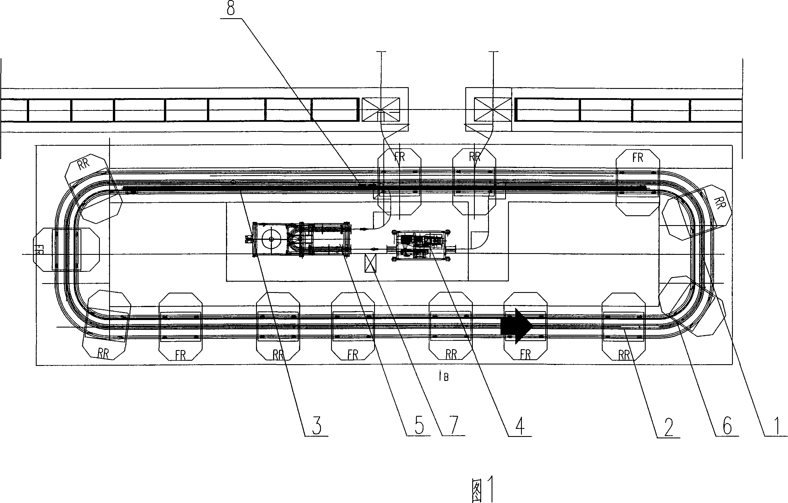
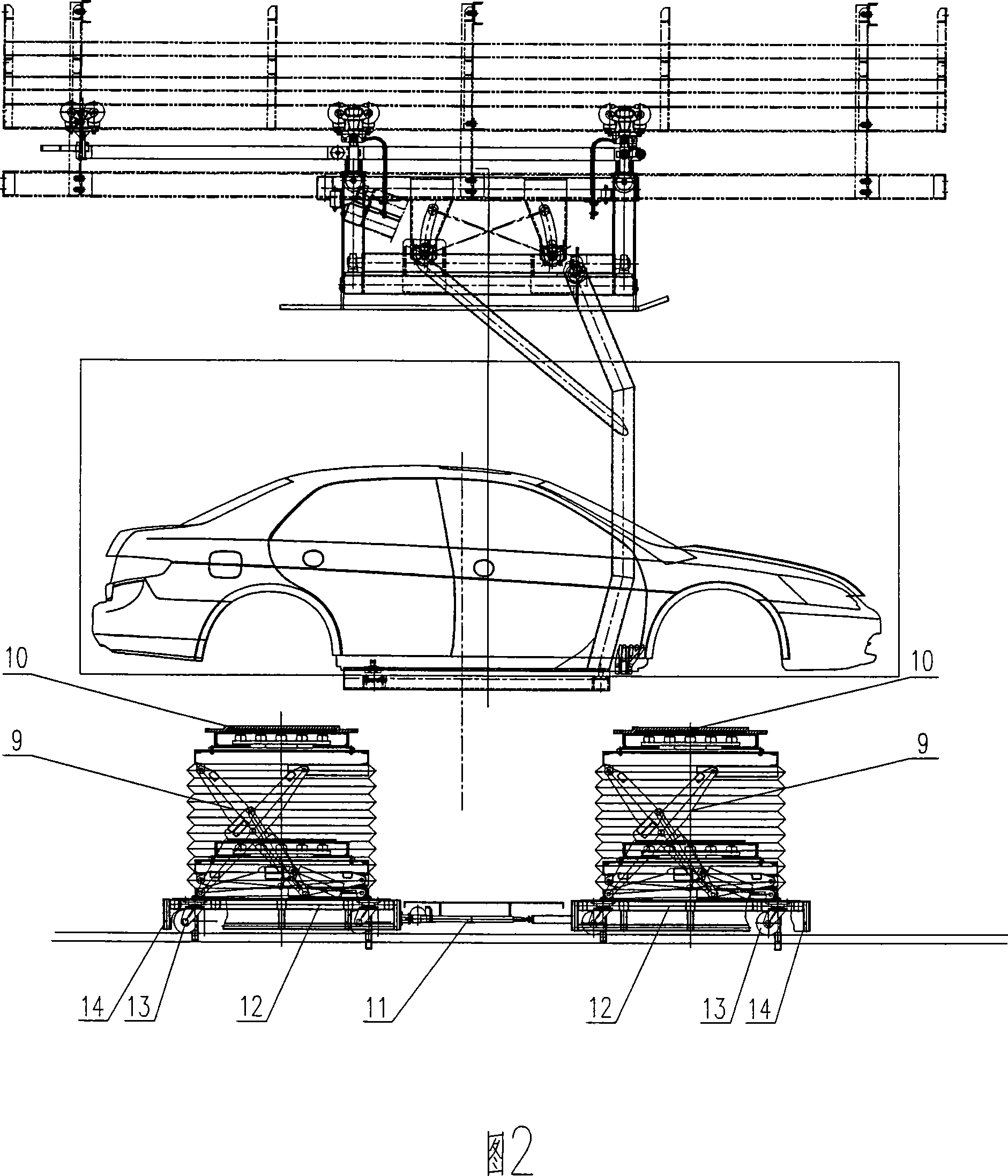
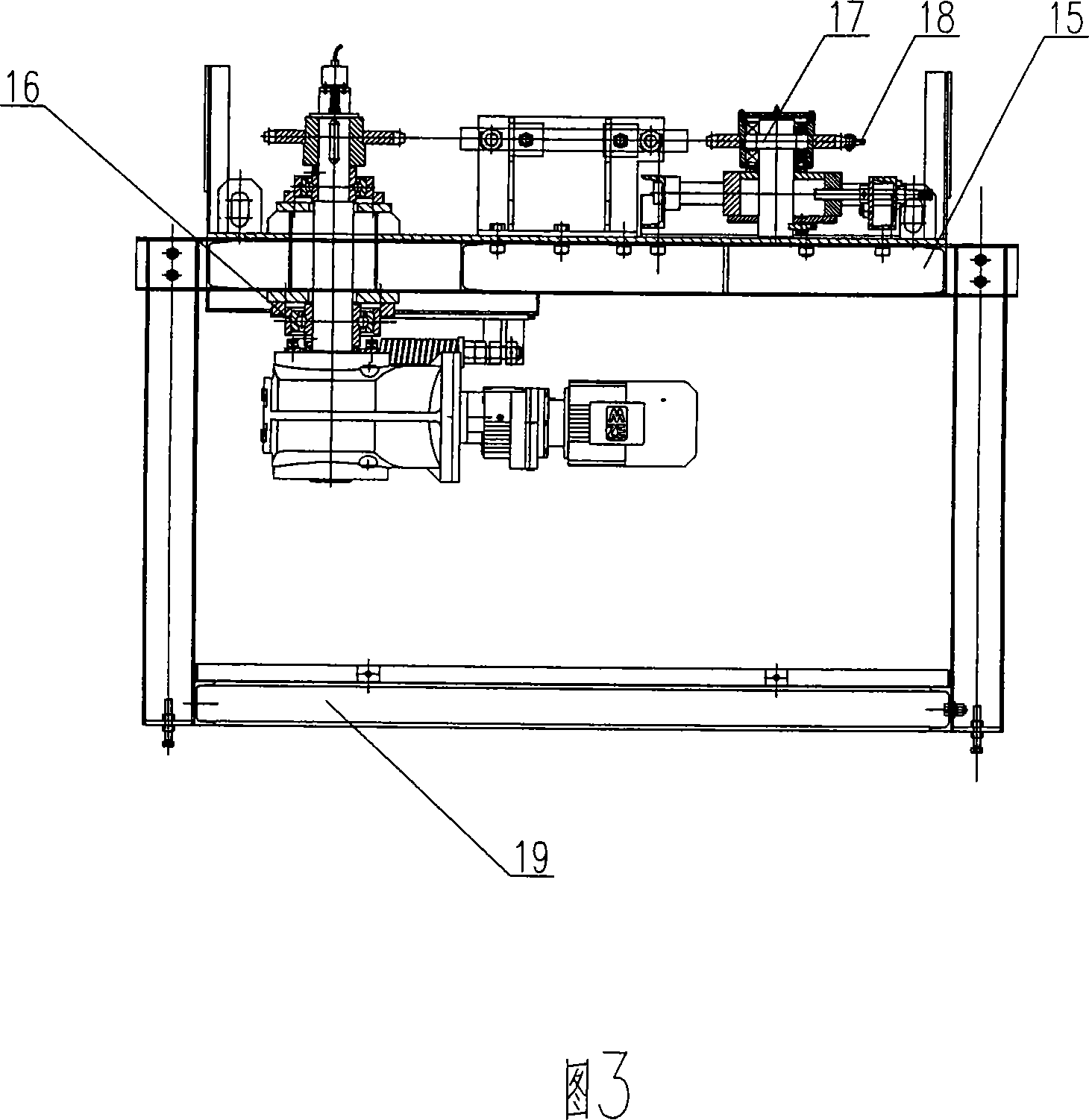
[0021] The present invention mainly consists of track 1, trolley 2, propulsion mechanism 3, driving device 4, tensioning device 5, chain 6, lubricating device 7, stopper 8, hydraulic jacking device 9, adjustable platform 10, electric push rod 11 , trolley support 12, universal wheel 13 and anti-collision mechanism 14 etc. are formed. Wherein, the driving frame 15 , the driving mechanism 16 , the tension wheel assembly 17 , the driving chain 18 and the underframe 19 etc. form the driving device 4 . Connecting track 20, tensioning frame 21, telescopic rail 22, tensioning curved rail 23, counterweight frame 24, counterweight 25, tensioning slide table 26 and fixed pulley assembly 27 etc. form tensioning device 5. Dolly 28, drive assembly 29, tension shaft assembly 30, support 31, chain 32, guide bar 33 and side plate 34 etc. form propulsion mechanism 3. ...


PUM


Abstract

The present invention relates to one kind of ring stroke variable front and back axle conveying system distributed in engine assembling line for engine and back axle installation, and belongs to the field of conveyer technology. The conveying system includes mainly one closed ring conveying line comprising one driving unit and one tightening unit connected to a track and chains mounted inside the track; bogies mounted on the closed ring conveying line; and one push mechanism mounted inside the closed ring conveying line. The present invention has simple compact and reasonable structure, capacity of adapting assembling of several type of vehicle, high work efficiency and other advantages.

Description

technical field [0001] The invention relates to a circular front and rear axle variable-stroke conveying system. The system is distributed on the engine assembly line body, and pushes a trolley through a ground push chain to realize the installation of the engine and the rear axle, and belongs to the technical field of conveyors. Background technique [0002] After the assembly of the engine and the rear axle conveying line is completed, when the vehicle body moves to the installation process of the engine and the rear axle, for the installation of the engine and the rear axle, the original working method is to rely entirely on manpower. In the installation process, relying entirely on manual work not only wastes working time, but also increases the labor intensity of the work. Contents of the invention [0003] The purpose of the present invention is to overcome the above disadvantages, thereby providing a variable-stroke conveying system for the circular front and rear a...

Claims


Application Information

Patent Timeline
IPC IPC(8): B65G37/00B65G47/04B65G35/00B65G17/00B65G17/30B65G23/44B62D65/18
Inventor 杨雷李卫领
Owner MIRACLE AUTOMATION ENG CO LTD
Why Eureka
Try Eureka