Sewing machine

A technology for sewing machines and sewing needles, which is applied to sewing machine components, needle holders for sewing machines, sewing equipment, etc., can solve problems such as troublesome work and inability to improve sewing efficiency, and achieves the improvement of sewing efficiency and sewing quality. Effect

Active Publication Date: 2008-01-09
JUKI CORP
View PDF2 Cites 17 Cited by
  • Summary
  • Abstract
  • Description
  • Claims
  • Application Information

AI Technical Summary

Problems solved by technology

[0011] According to the above situation, considering the change of the thickness of the object to be sewn or the sewing speed, it is necessary to adjust th...

Method used


Image

  • Sewing machine
  • Sewing machine
  • Sewing machine

Examples


Embodiment approach 2

[0086] (Structure of Sewing Machine)

[0087] As shown in Fig. 5 and Fig. 6, the sewing machine 10 is provided with a looping device to replace the kettle for winding the lower thread on the upper thread. The sewing machine 10 has a base portion 15 , a body portion 16 standing upward from the rear end of the base portion 15 , and an arm portion 17 extending forward from an upper portion of the body portion 16 .

[0088] A sewing machine motor 61 is provided in the base portion 15 , and a lower shaft 62 is connected to an output shaft of the sewing machine motor 61 . The lower shaft 62 is provided with a spreader drive cam 63 close to the needle thread and a looper drive cam 64 for driving the looper. Near one end of the lower shaft 62 , the lower shaft 62 is rotatably supported by the bearing 60 , and a lower pulley 65 is provided at one end of the lower shaft 62 .

[0089] A spreader drive lever 80 is provided on the spreader drive cam 63 so that power can be transmitted. ...

Embodiment approach 3

[0123] A sewing machine 20 in Embodiment 3 is a sewing machine in which the length ratio variable mechanism 4 of the sewing machine 1 in Embodiment 1 is changed to a length ratio variable mechanism 8 . Therefore, in Embodiment 3, the length ratio variable mechanism 8 having a different structure will be described, and other common structures will be given the same reference numerals, and description will be omitted.

[0124] (Structure of Sewing Machine)

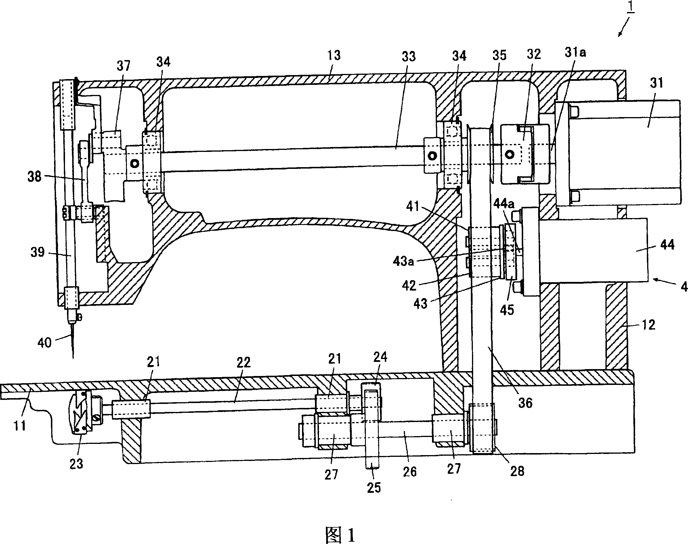
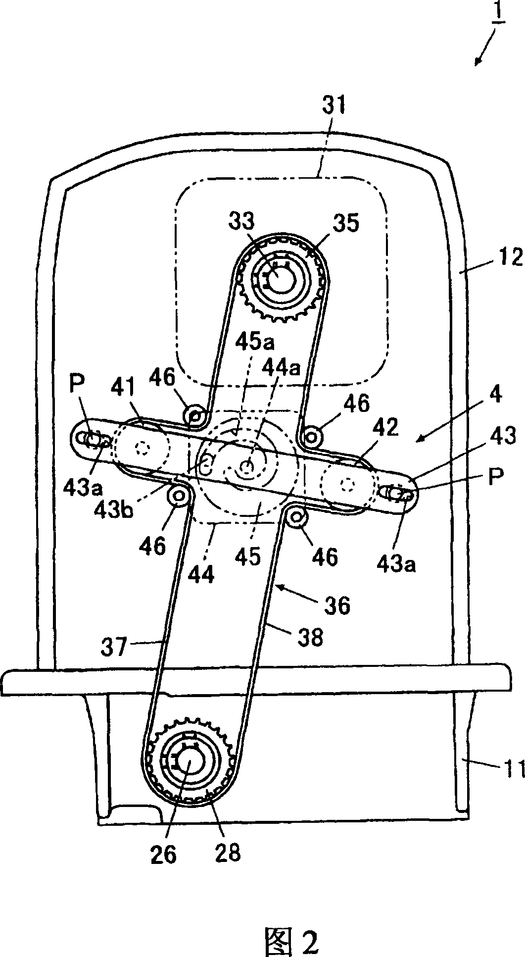
[0125] As shown in Figure 9, the length ratio variable mechanism 8 provided on the sewing machine 20 is arranged below the sewing machine motor 31, between the upper pulley 35 and the lower pulley 28, and changes the connection between the upper pulley 35 and the lower pulley 28. The length ratio of the bridging parts 37, 38.

[0126] As shown in Fig. 9 and Fig. 10, the length ratio variable mechanism 8 has: abutment parts 121, 122, which are in the position of pre-tensioning the two erection parts 37, 38, and the inside of...


PUM


Abstract

The present invention is to improve sewing efficiency through omitting the regulating work of the installation position of a kettle (or a beating ring device) generated through the thickness of the matter to sewing or the rotation delay of sewing speed as well as a kettle (or a beating ring device). A sartorius comprises an upper axis, which keeps a needle of a sewing needle move up and down; a lower axis, driving a sewing catching unit which catches the upper thread of the sewing needle to swing with the lower thread; a drive source, applying rotary drive on the upper axis and the lower axis; an upper axis rotary part, rotating along with the upper axis; a lower axis rotary part, rotating along with the lower axis; a drive transferring part, which loop shaped frames set on the upper axis rotary part and the lower axis rotary part, at the same time transfers the rotary drive of a rotary part rotated by means of the drive source to another rotary part, the drive transferring part ensures the length rate of two frame parts connecting with the position between the upper axis and the lower axis rotary part to be alter automatically through outside force.

Description

technical field [0001] The present invention relates to a sewing machine. Background technique [0002] Known is a lockstitch sewing machine that produces lockstitch stitches on a sewn object by knotting an upper thread and a lower thread. In the lockstitch sewing machine, an upper shaft that is rotationally driven by a sewing machine motor is provided on an arm portion of a sewing machine frame. The above-mentioned upper shaft is connected to the needle bar via a connecting rod. [0003] A lower shaft is rotatably provided on a base portion arranged below an arm portion of the sewing machine frame, and the lower shaft is connected to the upper shaft via a belt and a pulley so that the rotation of the upper shaft is transmitted to the lower shaft. The pot is fixed on the lower shaft, which accommodates the spool on which the lower thread is wound. [0004] Therefore, the kettle rotates while the needle bar moves up and down in conjunction with the rotation of the upper sh...

Claims


Application Information

Patent Timeline
IPC IPC(8): D05B69/00
CPCD05B57/30D05B69/30D05B55/14D05B69/12
Inventor 日塔隆
Owner JUKI CORP
Why Eureka
Try Eureka