Sewing machine

A technology for sewing machines and sewing needles, which is applied in the direction of sewing machine components, sewing machine needle seats, sewing equipment, etc., which can solve the problems of large moment of inertia of the kettle base, inability to perform high-speed sewing, and increased weight of the kettle base, etc., and achieve reduction error, reduce the moment of inertia, and realize the effect of reducing the manufacturing cost

Active Publication Date: 2013-06-26
JUKI CORP
View PDF6 Cites 6 Cited by
  • Summary
  • Abstract
  • Description
  • Claims
  • Application Information

AI Technical Summary

Problems solved by technology

However, if the above-mentioned structure is adopted, the weight of the whole kettle base increases, and a large and high-output motor is required as a rotary drive source of the kettle, and the strength of the structure supporting the kettle base is required, which increases the size of the sewing machine, heavyweight
In addition, since the weight of the pot base increases, it is difficult to rotate the pot at a high speed, resulting in the problem that high-speed sewing cannot be performed.
[0009] In addition, in the sewing machine of the above-mentioned Patent Document 1, the motor for rotating the kettle is mounted on the outer edge portion deviated from the rotational center line of the kettle base, so the moment of inertia of the kettle base becomes large, which becomes a further hindrance to the rotation of the kettle. Reason for high-speed motion
[0010] In addition, when the tank rotating motor is mounted on the rotating tank base, a slip ring is required as a sliding contact to supply power to the motor. This collector ring has the following problems, that is, the weight of the kettle base is further increased, the size is increased, and the sewing speed is reduced.

Method used


Image

  • Sewing machine
  • Sewing machine
  • Sewing machine

Examples


no. 1 approach

[0144] based on Figure 1 to Figure 12 , the first embodiment of the present invention will be described.

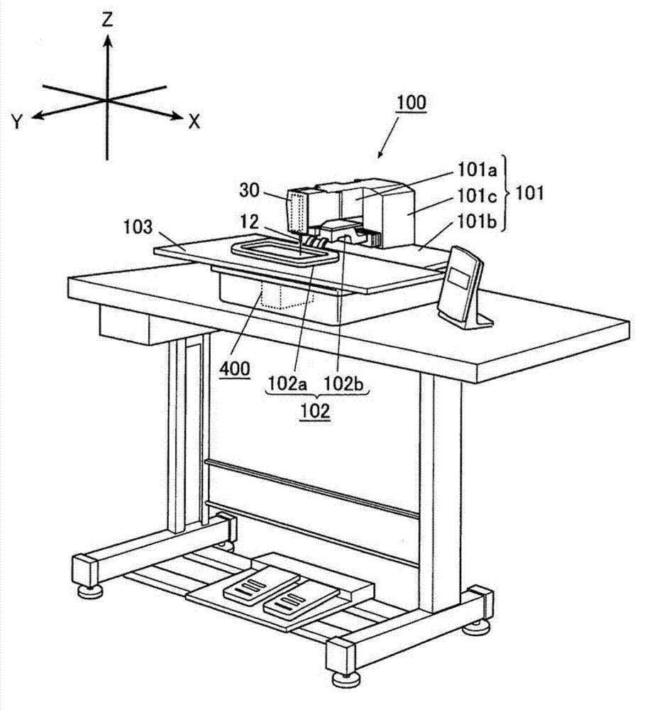
[0145] The sewing machine 100 described below as this embodiment is a so-called electronic cycle sewing machine, and has a holding frame as a cloth holding part for holding the cloth as a sewn object to be sewn. By moving relative to the sewing needle, a sewing pattern based on predetermined sewing data is formed on the cloth held by the holding frame.

[0146] Here, the direction in which the sewing needle 11 described later moves up and down is defined as the Z-axis direction (up-and-down direction), and a horizontal direction perpendicular to this direction is defined as the X-axis direction (left-right direction). Another orthogonal horizontal direction is defined as the Y-axis direction (front-back direction).

[0147] like figure 1 and figure 2 Shown, sewing machine 100 has sewing machine frame 101, and this sewing machine frame 101 is made up of following par...

no. 2 approach

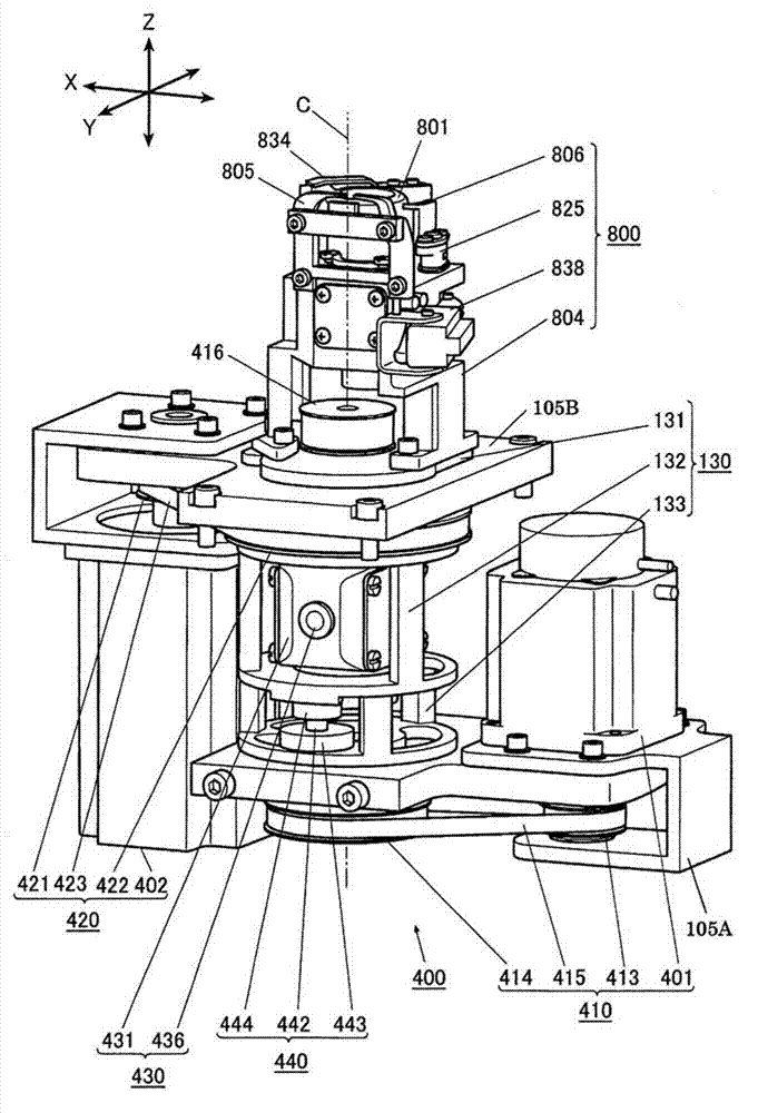
[0282] A second embodiment of the present invention will be described. In the sewing machine according to the second embodiment, a differential transmission mechanism 400A having a rotary operation portion 420A, a differential mechanism portion 430A, and a rotation interlocking portion 440A is mounted. The rotation interlocking part 440A has a structure different from the rotation operation part 420, the differential mechanism part 430, and the rotation interlocking part 440 of the sewing machine 100 mentioned above.

[0283] In the following description, only the difference between the differential transmission mechanism 400A and the differential transmission mechanism 400 will be described, and the same components will be given the same reference numerals, and redundant descriptions will be omitted.

[0284] exist Figure 13 and Figure 14 Among them, the rotating operation part 420A is different from the above-mentioned rotating operation part 420 in that it does not appl...


PUM


Abstract

The invention provides a sewing machine, wherein small lightweight and action accelation surrounding a boiler are achieved. The sewing machine includes the components as following: a needle bar, a boiler, a sewing machine motor, a boiler driven motor, a needle bar rotating mechanism, a boiler rotating platform; a needle rotating motor, which enbles the needle bar to rotate; a boiler rotating motor, which enables the boiler rotating platform to rotate, and a differential transmission mechanism, which is provided with an input shaft and an output shaft for transmitting a boiler rotating force. The differential transmission mechanism comprises the components as following: a support frame, which is arranged surrounding the input shaft and the output shaft on a center line to rotate; a transmitter, which is supported on the support frame, wherein the rotating force is transmitted between the input shaft and the output shaft; a driven part, which is arranged on a boiler rotating platform or the support frame and is rotated through the boiler rotating motor; and a rotation linkage mechanism, wherein the boiler rotating platform and the support frame are driven to rotate at the same direction by the rotating force from the driven part, and the boiler rotating platform is rotated with the rotation amount twice as much as the rotation amount of the support frame.

Description

technical field [0001] The present invention relates to a sewing machine in which the whole kettle mechanism is rotated. Background technique [0002] Currently, there is known a sewing machine that forms stitches while conveying a to-be-sewn object in any direction in the X-Y direction. In the case of using a single-needle sewing machine with one needle as this sewing machine, there is a case where the upper thread becomes helical and stitches are formed along with its conveying direction, that is, the sewing direction, that is, there is a case where so-called winding occurs. In the case of stitches, in order to prevent this phenomenon and form a so-called ideal stitch, a mechanism for rotating (rotating) the needle bar and the kettle mechanism around the axis of the needle bar is provided. For example, in the case of conveying the object to be sewn in any direction in the X-Y direction for each stitch, when sewing in the sewing direction where wrapping stitches are likely...

Claims


Application Information

Patent Timeline
Patent Type & Authority Applications(China)
IPC IPC(8): D05B27/00D05B55/14D05B69/02
Inventor 月冈高志公文哲柳泽理人
Owner JUKI CORP
Why Eureka
Try Eureka