
Material moving device and sleeve slit machine

A material moving and material plate technology is applied in the field of sleeve fork machines, which can solve the problems of easy skipping of stitches, unstable thread loops, affecting the sewing quality of sleeve forks, etc., and achieves the effect of improving sewing quality and forming stable thread loops.

Active Publication Date: 2020-03-27
迈卡有限责任公司
View PDF7 Cites 6 Cited by
  • Summary
  • Abstract
  • Description
  • Claims
  • Application Information

AI Technical Summary

Problems solved by technology

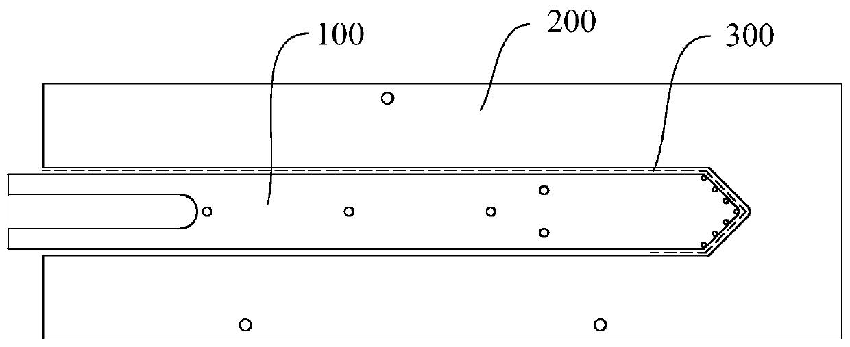
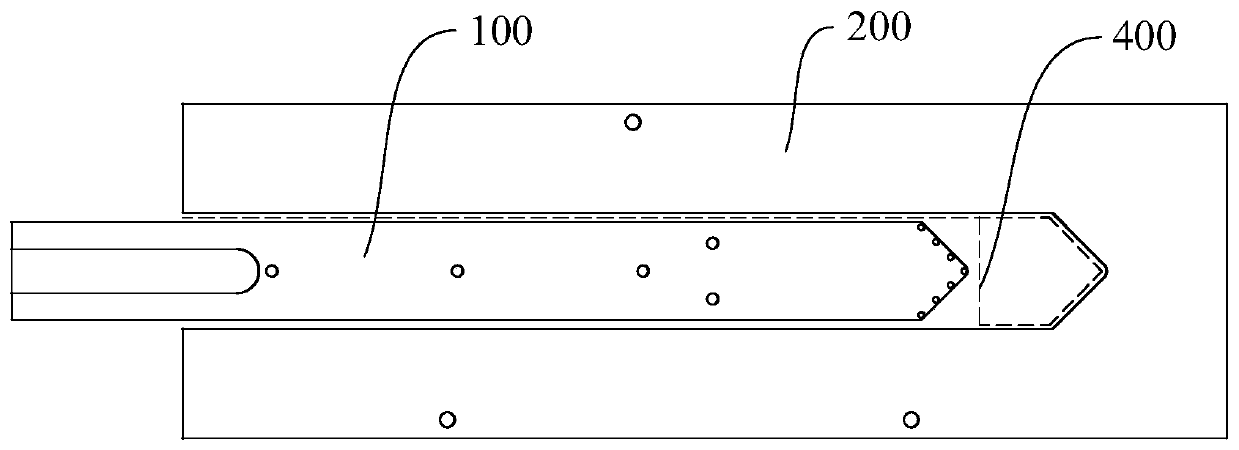
[0006] But when the inner hold-down plate 100 is in the second working position and the sleeve fork machine is sewing in the second sewing area 400, since there is no structure to compact the exposed sewing material in the second sewing area 400, the inner The end of the pressing plate 100 close to the second sewing area 400 is a sharp end, which causes a large change in the thickness of the sewing material, thereby causing the thread loop to be unstable during the sewing process, and it is easy to cause skipped stitches, especially When sewing double horizontal stitches, it is easier to skip stitches, which will affect the sewing quality of sleeve forks

Method used


Image

  • Material moving device and sleeve slit machine
  • Material moving device and sleeve slit machine
  • Material moving device and sleeve slit machine

Examples


Embodiment Construction

[0030] The implementation of the present invention will be illustrated by specific specific examples below, and those skilled in the art can easily understand other advantages and effects of the present invention from the contents disclosed in this specification.

[0031] It should be noted that the structures, proportions, sizes, etc. drawn in the drawings of this specification are only used to match the content disclosed in the specification, for those who are familiar with this technology to understand and read, and are not used to limit the conditions for the implementation of the present invention. Therefore, there is no technical substantive meaning, and any modification of structure, change of proportional relationship or adjustment of size shall still fall within the scope of the disclosure of the present invention without affecting the functions and objectives of the present invention. within the scope of technical content. At the same time, terms such as "upper", "lo...


PUM


Abstract

The invention provides a material moving device. The material pressing device comprises an outer material pressing plate and an inner material pressing plate which are used for pressing sewing materials. An accommodating cavity is formed in the outer pressing plate; the inner pressing plate is movably arranged in the accommodating cavity and is provided with a first working position and a second working position, a first sewing area is correspondingly formed between the outer edge of the inner pressing plate and the cavity wall of the accommodating cavity, and a second sewing area is correspondingly formed between the top end of the inner pressing plate and the end part of the accommodating cavity; the material moving device further comprises a pressing pad capable of moving in the direction close to or away from the containing cavity. When the inner pressing plate is located at the second working position, the pressing pad is located in the second sewing area and presses the sewing material exposed in the second sewing area, and a third sewing area allowing the sewing material to be exposed is formed between the top end of the inner pressing plate and the pressing pad. By additionally arranging the pressing pad, it is guaranteed that sewing materials in the second sewing area can be firmly pressed, when a machine needle conducts transverse sewing in the third sewing area, a thread ring is formed stably, and the phenomenon of needle jumping is avoided.

Description

technical field [0001] The invention relates to the field of garment production, in particular to a material transfer device and a sleeve fork machine equipped with the material transfer device. Background technique [0002] Sleeve machines are commonly used in the production of various garments such as shirts. Typically, a cuff is a strip of fabric that is folded and sewn around the edge of the cut made from the edge of the shirt; for example: a cuff is sewn at the bottom of each sleeve at the cut that corresponds to the matching cuff, forming a cuff. A reinforcement that is used to process one or more buttonholes and provides a decorative aesthetic. [0003] The stitching of the yoke usually consists of a suture extending from the edge of the sleeve along the longitudinal direction of the yoke and towards the inside of the sleeve, and then the suture extends along the transverse direction of the yoke to the folded part of the yoke on the sleeve , the suture extends along...

Claims


Application Information

Patent Timeline
Patent Type & Authority Applications(China)
IPC IPC(8): D05B29/00D05B29/02D05B35/06
CPCD05B29/00D05B29/02D05B35/066A41H33/00D05B35/02
Inventor 舒勤业李广伟简路易奇·托马塞利安德烈·托马塞利
Owner 迈卡有限责任公司
Learn More