Substrate holding and rotating device, substrate processing device equipped with same, and substrate processing method

a technology of holding and rotating device and substrate, which is applied in the direction of cleaning process and apparatus, chemistry apparatus and processes, and using liquids to clean up, etc. it can solve the problems of insufficient inability to move the vertically movable member sufficiently close to the lower surface of the substrate, and inability to provide centrifugal force or lift force. , to achieve the effect of suppressing the intrusion of treatment liquid mist, stably

Active Publication Date: 2016-04-07
DAINIPPON SCREEN MTG CO LTD
View PDF1 Cites 26 Cited by
  • Summary
  • Abstract
  • Description
  • Claims
  • Application Information

AI Technical Summary

Benefits of technology

[0050]In the still another embodiment of the present, the substrate treatment method may further include an inert gas supplying step of supplying an inert gas to a space defined between the substrate being rotated and the protection disk located at the adjacent position in the treatment liquid supplying step. In this method, the inert gas can be supplied to the space defined between the protection disk and the lower surface of the substrate. This further suppresses the adhesion of the treatment liquid mist to the lower surface of the substrate.
[0051]In the still another embodiment of the present, the protection disk may have a restriction portion provided on an upper surface portion thereof to be opposed to a peripheral edge of the substrate held by the holding member. In this case, the substrate treatment method may further include the step of restricting an inert gas flow passage by the restriction portion in the inert gas supplying step. In this method, the inert gas flow passage is restricted on the peripheral edge of the substrate, so that an inert gas stream is ejected at a higher speed outward from a gap defined between the protection disk and the peripheral edge of the substrate. This more reliably suppresses the intrusion of the treatment liquid mist into the space defined between the protection disk and the lower surface of the substrate.
[0052]In the still another embodiment of the present, the inert gas supplying step may include the step of ejecting the inert gas radially toward the peripheral edge of the substrate held by the holding member from the rotation center of the turntable. In this method, the inert gas stream flowing toward the peripheral edge of the substrate from the rotation center of the turntable can be stably formed. This more reliably suppresses the intrusion of the treatment liquid mist into the space defined between the protection disk and the lower surface of the substrate.
[0053]In the still another embodiment of the present, the substrate treatment method may further include the step of covering the space defined between the substrate held by the holding member and the turntable from a lateral side by a lateral side covering portion attached to the turntable in the lower surface covering step. In this method, an ambient, atmosphere is less liable to be caught into the space defined between the turntable and the lower surface of the substrate, so that a gas stream flowing around the turntable can be stabilized. This suppresses the generation of the treatment liquid mist, making it possible to perform a higher-quality substrate treatment.

Problems solved by technology

With these arrangements, however, it is impossible to move the vertically movable member sufficiently close to the lower surface of the substrate, because the centrifugal force or the lift force cannot be sufficiently generated when the substrate is rotated at a lower rotation speed.
As a result, the mist generated during the substrate treatment process is liable to adhere to the lower surface of the substrate.
Where an upper surface of the substrate being rotated is scrubbed with a brush, for example, the rotation speed of the substrate is about 100 rpm, making it impossible to sufficiently provide the centrifugal force or the lift force.
Therefore, mist of a treatment liquid is liable to intrude into a space defined between the lower surface of the substrate and the vertically movable member during the scrubbing of the upper surface of the substrate, thereby contaminating the lower surface of the substrate.
However, these arrangements each have a complicated structure, because driving means for the vertical driving is incorporated in a rotation system including the turntable and the vertically movable member, and requires supply of a driving force.
This may result in generation of particles, which may adversely influence the substrate treatment.

Method used


Image

  • Substrate holding and rotating device, substrate processing device equipped with same, and substrate processing method
  • Substrate holding and rotating device, substrate processing device equipped with same, and substrate processing method
  • Substrate holding and rotating device, substrate processing device equipped with same, and substrate processing method

Examples


first embodiment

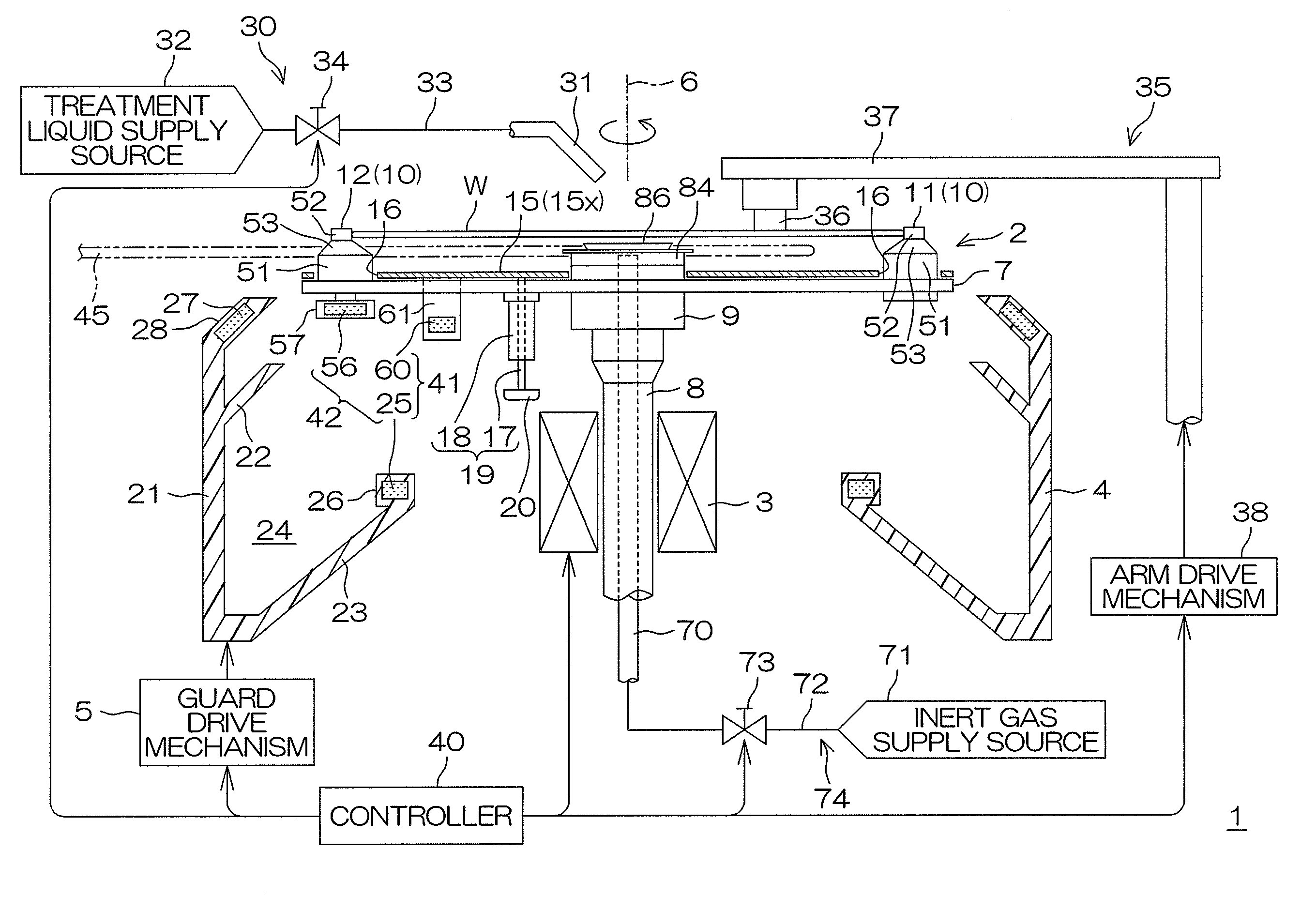
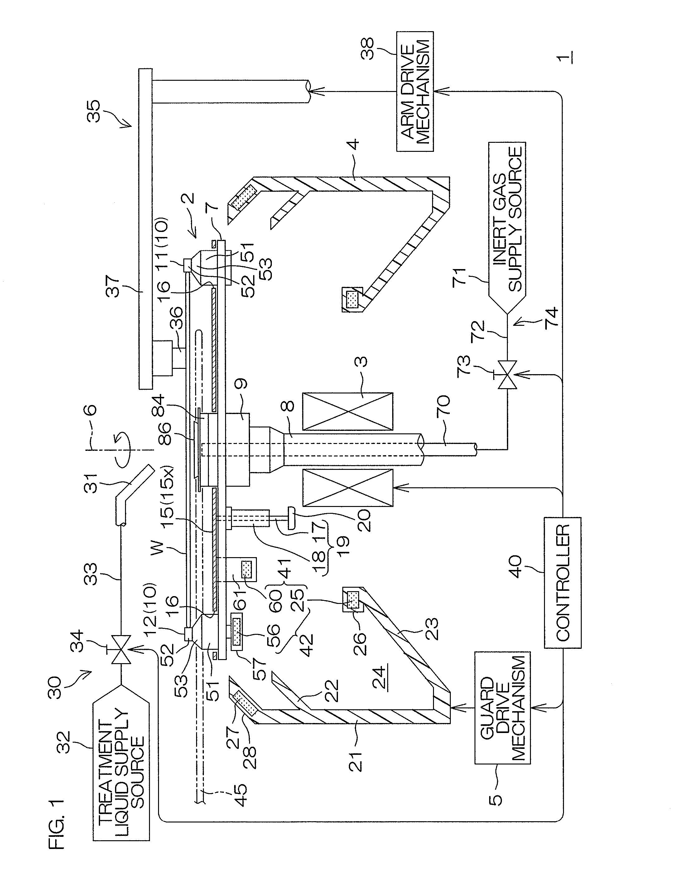
[0077]FIG. 1 is a schematic sectional view for explaining the construction of a substrate treatment apparatus according to the present invention. The substrate treatment apparatus 1 is an apparatus of a single substrate treatment type adapted to treat a single substrate W (e.g., a semiconductor wafer or the like) at a time. The substrate treatment apparatus 1 includes a spin chuck 2, a rotative drive mechanism 3, a splash guard 4 and a guard drive mechanism 5.

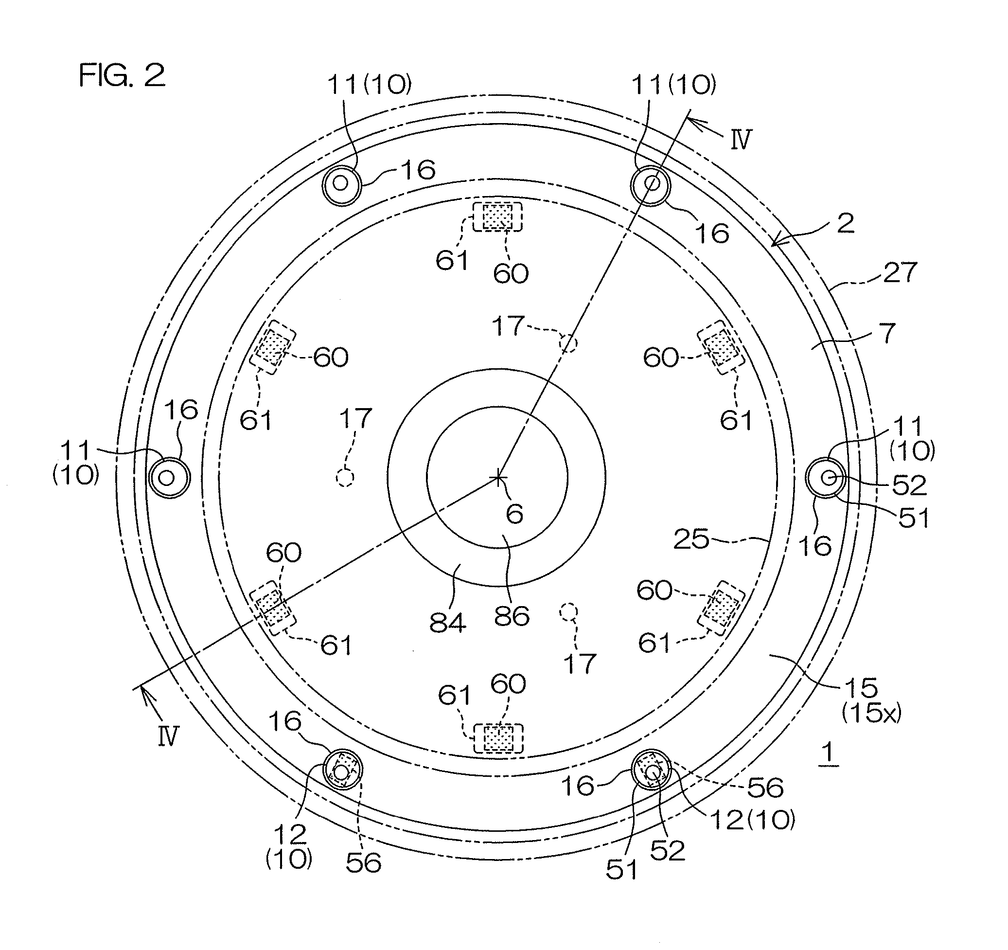
[0078]The spin chuck 2 includes a turntable 7 rotatable about a vertical rotation axis 6. A rotation shaft 8 is connected to a lower surface of the turntable 7 at a rotation center via a boss 9. The rotation shaft 8 extends vertically, and is configured to receive a driving force from the rotative drive mechanism 3 to be rotated about the rotation axis 6. The rotative drive mechanism 3 may be, for example, an electric motor employing the rotation shaft 8 as a driving shaft. The spin chuck 2 further includes a plurality of holdi...

second embodiment

[0124]In the second embodiment, more specifically, the magnetic levitation mechanism 41 includes protection disk permanent magnets 60, a disk lifting permanent magnet 64 and a lift actuator 65. The disk lifting permanent magnet 64 is an annular permanent magnet piece disposed in a horizontal plane about the rotation axis 6, and has an annular magnetic pole opposed to the protection disk permanent magnets 60 from a lower side. The magnetic pole has the same polarity as lower magnetic poles of the protection disk permanent magnets 60. Therefore, the disk lifting permanent magnet 64 generates an upward repulsive magnetic force with respect to the protection disk permanent magnets 60. The disk lifting permanent magnet 64 is incorporated and retained in an annular magnet retaining member 66. An actuation shaft 65a of the lift actuator 65 is connected to the magnet retaining member 66.

[0125]The lift actuator 65 is, for example, an air cylinder, which is configured to move up and down the ...

third embodiment

[0129]In the third embodiment, the magnetic levitation mechanism 41 includes protection disk permanent magnets 60, a disk lifting permanent magnet 64 and a lift actuator 111. The disk lifting permanent magnet 64 is an annular permanent magnet piece disposed in a horizontal plane about the rotation axis 6, and has an annular magnetic pole opposed to the protection disk permanent magnets 60 from a lower side. The magnetic pole has the same polarity as lower magnetic poles of the protection disk permanent magnets 60. Therefore, the disk lifting permanent magnet 64 generates an upward repulsive magnetic force with respect to the protection disk permanent magnets 60. The disk lifting permanent magnet 64 is incorporated and retained in an annular magnet retaining member 66. An actuation member 111a of the lift actuator 111 is connected to the magnet retaining member 66.

[0130]The lift actuator 111 includes a ball screw mechanism 112 and an electric motor 113, and is configured to verticall...


PUM


Abstract

A substrate treatment apparatus includes a turntable, a rotative drive unit, a holding pin provided on the turntable, a protection disk for covering a lower surface of a substrate, and a magnetic levitation mechanism that levitates the protection disk from the turntable. The protection disk is vertically movable relative to the turntable between a lower position and an adjacent position above the lower position and close to a lower surface of the substrate. The magnetic levitation mechanism includes a protection disk permanent magnet and an annual guard permanent magnet held by a splash guard. When a guard drive mechanism moves up the splash guard, the protection disk is levitated from the turntable and held at the adjacent position by a magnetic repulsive force generated between the permanent magnets.

Description

FIELD OF THE ART[0001]The present invention relates to a substrate holding and rotating device, a substrate treatment apparatus including the device, and a substrate treatment method. Exemplary substrates to be held or treated include semiconductor wafers, substrates for liquid crystal display devices, substrates for plasma display devices, substrates for FED (Field Emission Display) devices, substrates for optical disks, substrates for magnetic disks, substrates for magneto-optical disks, substrates for photo masks, ceramic substrates, and substrates for solar cells.BACKGROUND ART[0002]Patent Document 1 discloses a substrate rotating and holding device for a substrate spin treating apparatus. The substrate rotating and holding device includes a turntable to be rotated by rotation means, and support means which horizontally positions a substrate held by the turntable so as to space the substrate a predetermined distance from a surface of the turntable. A vertically movable member ha...

Claims


Application Information

Patent Timeline
Patent Type & Authority Applications(United States)
IPC IPC(8): B08B3/10H01L21/67H01L21/02H01L21/687
CPCB08B3/10H01L21/68792H01L21/02052H01L21/67023H01L21/68728H01L21/67046H01L21/67051B08B3/02
Inventor KATO, HIROSHI
Owner DAINIPPON SCREEN MTG CO LTD
Why Eureka
Try Eureka