Compressor crankshaft, particularly refrigerant compressor crankshaft, and method for grinding such a crankshaft

A technology for compressor crankshafts and refrigeration compressors, applied in the field of compressor crankshafts, can solve problems such as long fixed cycle time, and achieve the effect of improving accuracy

Active Publication Date: 2008-01-09
SECOP GMBH
View PDF2 Cites 4 Cited by
  • Summary
  • Abstract
  • Description
  • Claims
  • Application Information

AI Technical Summary

Problems solved by technology

Furthermore, the grinding tool is at best moved against the shaft section at a relatively low speed so that a relatively long constant cycle time occurs

Method used


Image

  • Compressor crankshaft, particularly refrigerant compressor crankshaft, and method for grinding such a crankshaft
  • Compressor crankshaft, particularly refrigerant compressor crankshaft, and method for grinding such a crankshaft
  • Compressor crankshaft, particularly refrigerant compressor crankshaft, and method for grinding such a crankshaft

Examples


Embodiment Construction

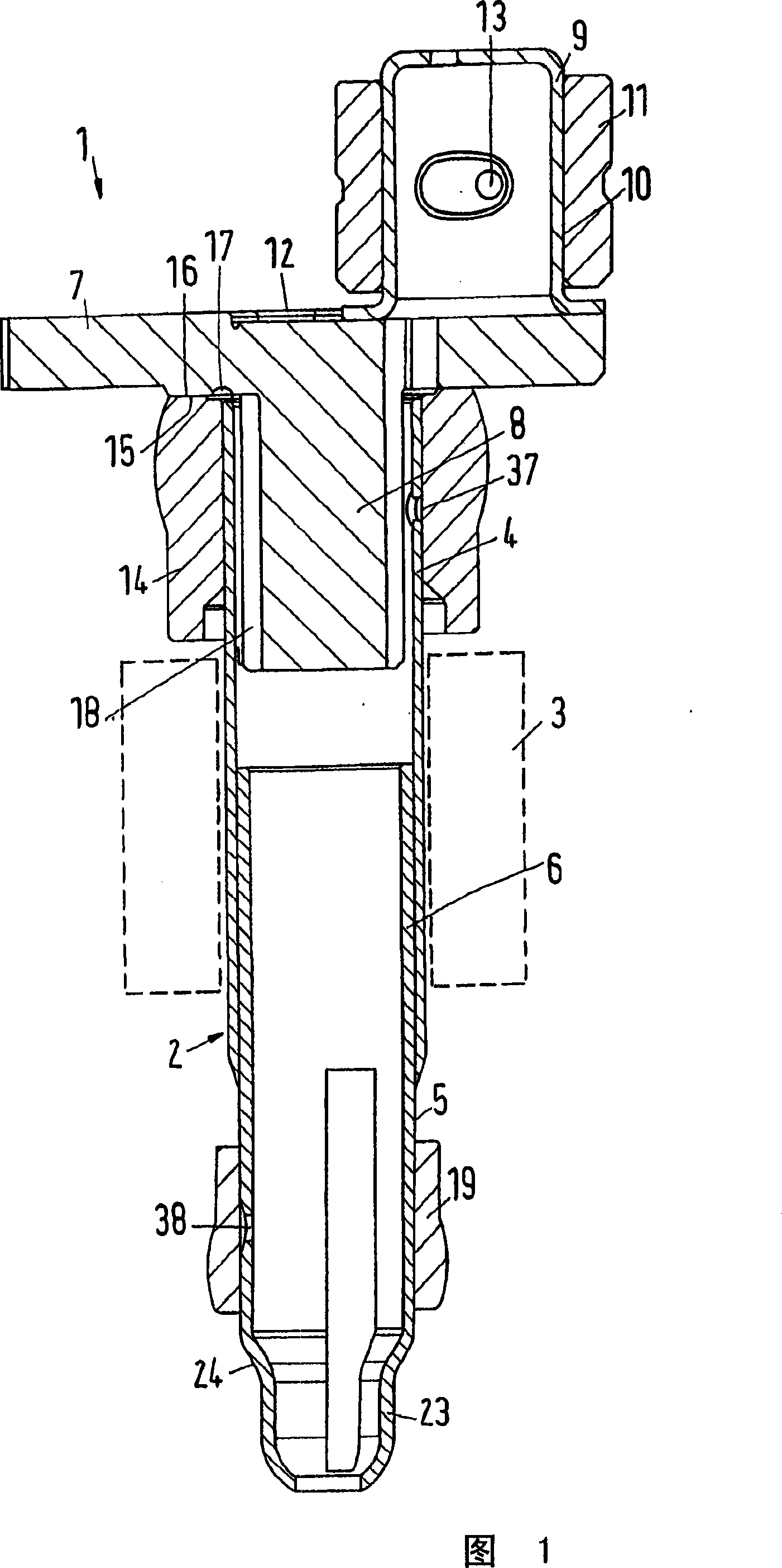
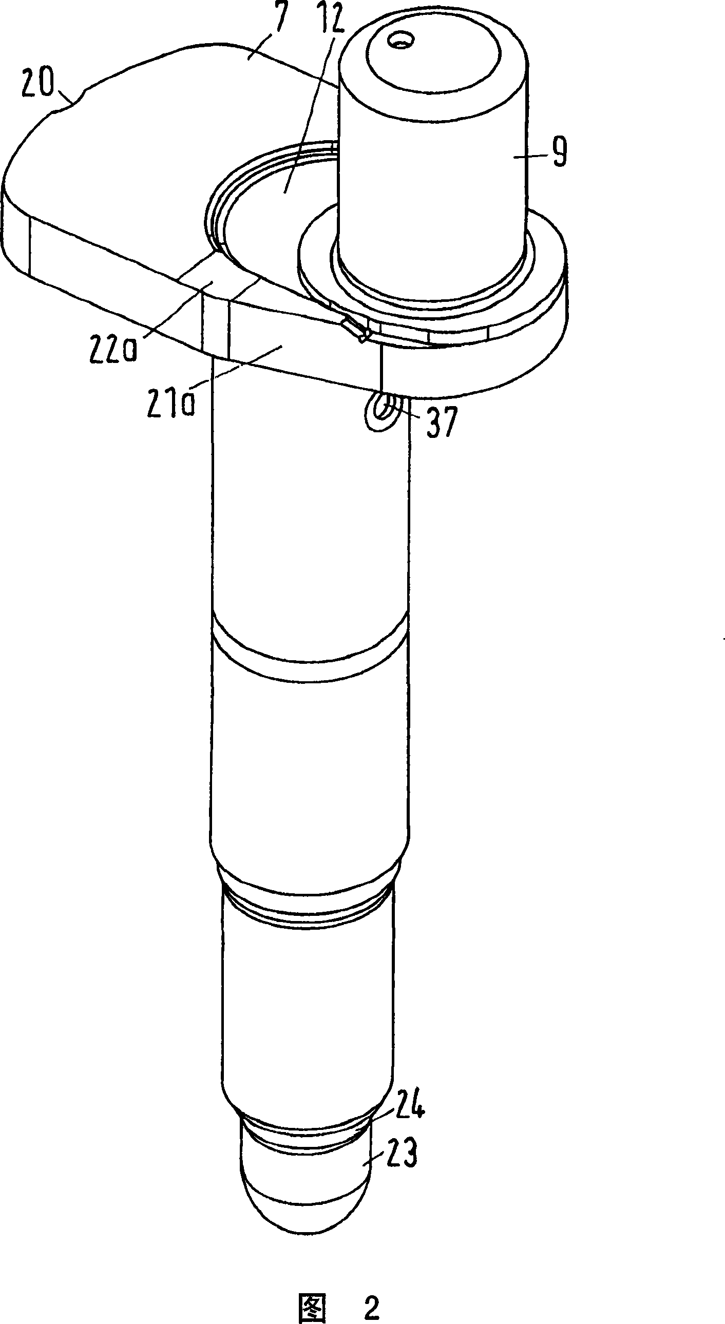
[0031] As shown in FIG. 1 , the crankshaft 1 of the refrigeration compressor has a shaft element 2 which is configured to be connected to a rotor 3 of an electric drive motor, which is only shown schematically. The shaft element 2 is made of two telescopically connecting parts 4, 5 which are connected to each other at overlapping portions 6 by means of welding, for example.

[0032] Such a crankshaft 1 is generally driven in the position shown in which the shaft elements are oriented substantially vertically. For reasons of clarity, directions will be referred to in the following as "upper" or "lower" or similar terms, the terms referring to the views of FIGS. 1 , 2 and 4 . However, no definite point of spatial orientation of the crankshaft 1 is given.

[0033] The conversion element 7 is located at the upper end of the part 4 of the shaft element 2 . The conversion element 7 is produced as a sintered or extruded molded part, in particular a cold-formed part. It can thus be...


PUM


Abstract

The invention concerns a compressor crankshaft, particularly a refrigerant compressor crankshaft ( 1 ) and a method for manufacturing such a crankshaft, with a shaft element ( 2 ), a crank pin ( 9 ) located eccentrically to the shaft element and a transition element ( 7 ) between the shaft element ( 2 ) and the crank pin ( 9 ). The purpose of the invention is to keep the manufacturing costs low. For this purpose, it is ensured that along its circumference the transition element ( 7 ) has at least one first reference point ( 20 ) and one second reference point ( 21 a , 21 b), with which the transition element ( 7 ) can be positioned in a holding fixture ( 25 ) of a working machine.

Description

technical field [0001] The invention relates to a compressor crankshaft, in particular a refrigeration compressor crankshaft, having a shaft part, a crank pin arranged eccentrically with respect to the shaft part and a switching element between the shaft part and the crank pin. Furthermore, the present invention relates to a method of grinding a compressor crankshaft, in particular a refrigeration compressor crankshaft, having a shaft part, a crank pin and a conversion element between the shaft part and the crank pin , the circumference of the shaft part is ground. Background technique [0002] Hereinafter, the invention will be described on the basis of a refrigeration compressor crankshaft. [0003] Refrigeration compressors in the form of piston piston compressors usually have a crankshaft, the shaft part of which is connected in a non-rotatable manner to the rotor of the drive motor. The conversion element rotates around the shaft element, and then generates the rotati...

Claims


Application Information

Patent Timeline
Patent Type & Authority Applications(China)
IPC IPC(8): F16C3/08B24B5/42F16C3/10F04B35/01B23B5/22
CPCB24B5/421F16C3/04F04B39/0094Y10T74/2173
Inventor F·H·伊弗森H·O·拉森M·诺门森E·汉德克
Owner SECOP GMBH
Why Eureka
Try Eureka