Wiring machine platform and wiring method

A technology of wire bonding machine and wire bonding head, which is applied in the fields of electrical components, semiconductor/solid-state device manufacturing, circuits, etc. It can solve the problems that the speed of wire bonding is difficult to be significantly improved, and the production line cannot be expanded, so as to achieve the effect of increasing the speed

Active Publication Date: 2008-01-09
ADVANCED SEMICON ENG INC
View PDF0 Cites 4 Cited by
  • Summary
  • Abstract
  • Description
  • Claims
  • Application Information

AI Technical Summary

Problems solved by technology

Traditionally, only a single wire bonding machine can be used to bond a substrate, and it is difficult to significantly increase the wire bonding speed when the production line cannot be expanded.

Method used


Image

  • Wiring machine platform and wiring method
  • Wiring machine platform and wiring method
  • Wiring machine platform and wiring method

Examples


Embodiment Construction

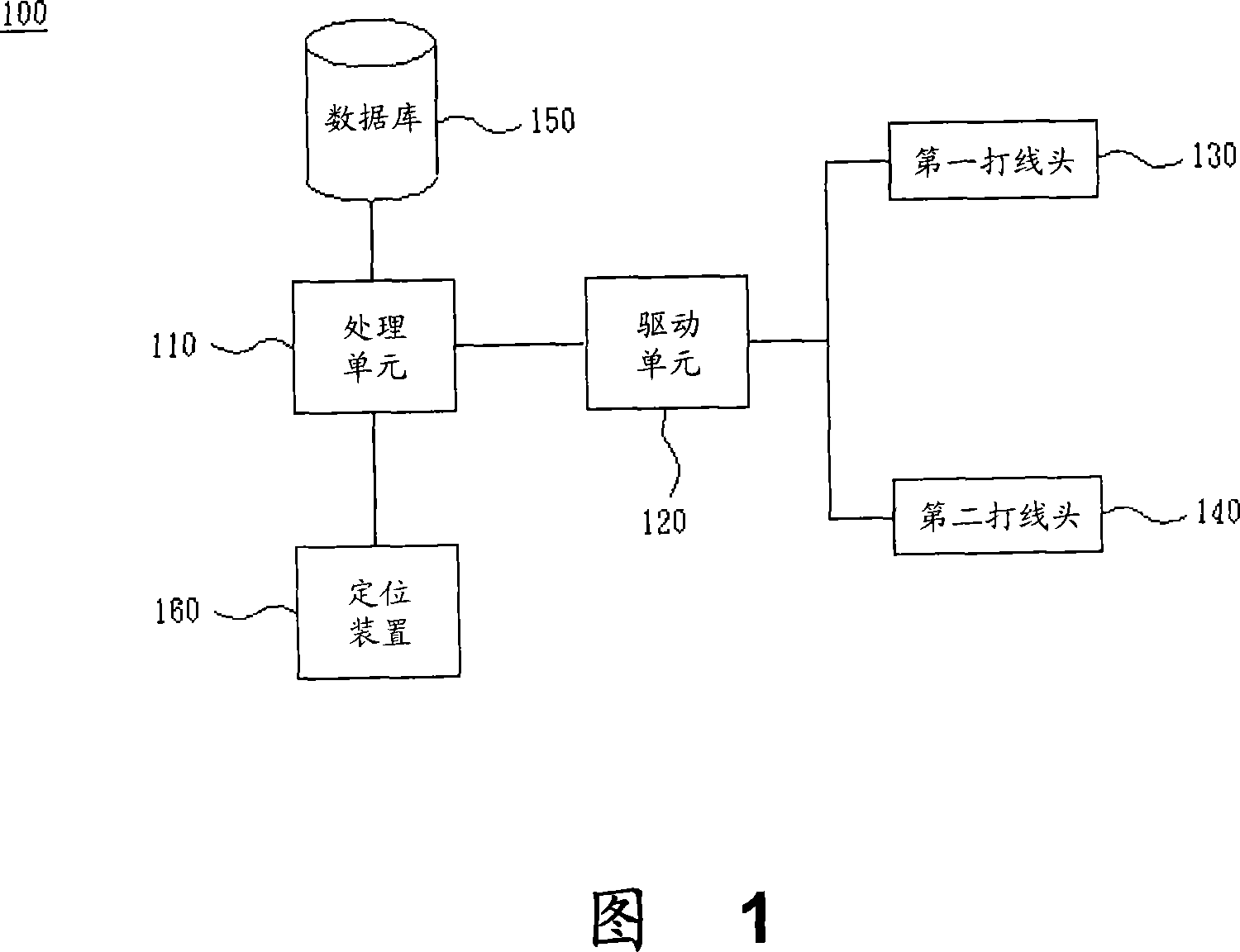
[0024] Please refer to FIG. 1 , which shows a functional block diagram of a wire bonding machine according to the present invention. The wire bonding machine 100 is used for simultaneously bonding at least one first chip and a second chip (not shown in the figure) on a substrate. The wire bonding machine 100 includes a first wire bonding head 130 and a second wire bonding head 140 , a driving unit 120 and a processing unit 110 . The driving unit 120 is used to move the first wire-bonding head 130 and the second wire-bonding head 140, such as a driving motor; the processing unit 110 is used to output control commands to the driving unit 120 to control the first wire-bonding head 130 and the second wire-bonding head 140 The moving mode and wire bonding action, the processing unit 110 is, for example, a microprocessor or an application specific integrated circuit (ASIC).

[0025] In addition, the wire bonding machine 100 further includes a database 150 for storing operation para...


PUM


Abstract

The invention is concerned with the thread feeder arm that is used to process thread to at least the first chip and the second chip on the basis synchronously, includes: at least the first thread head and the second thread head, the driving unit, the processing unit, the database. It is: the driving unit uses to move the first thread head and the second thread head; the processing unit uses to output the controlling order to the driving unit in order to control the first thread head and the second thread head; the database stores the operating parameter data, the processing unit control the first thread head and the second thread head according to the operating parameter data.

Description

technical field [0001] The present invention relates to a wire bonding machine and a wire bonding method thereof, and in particular to a wire bonding machine with at least two wire bonding heads for simultaneous wire bonding and a wire bonding method thereof. Background technique [0002] With the advent of the era of consumer electronics, the demand for various integrated circuits (ICs) has also increased rapidly in recent years. Therefore, it also increases the demand for IC packaging capacity. Therefore, how to increase the efficiency and production capacity of packaging under the existing technology has become the key to enhance the competitiveness of each packaging factory. [0003] The IC needs to go through a wire-bonding process to connect the electrical contacts on the IC to the pins on the substrate, and then package it to become an electronic component that can be assembled. Traditionally, only a single wire bonding machine can be used to bond a substrate, and i...

Claims


Application Information

Patent Timeline
Patent Type & Authority Applications(China)
IPC IPC(8): H01L21/60
Inventor 唐和明苏高明李德章翁肇甫林千琪蔡佳蓉魏志男杨淞富
Owner ADVANCED SEMICON ENG INC
Why Eureka
Try Eureka