LED module
A technology of light-emitting diodes and modules, applied in electrical components, electric solid-state devices, circuits, etc., can solve the problems of inconvenience, no heat dissipation path, and shortened service life, so as to reduce steps and time, ensure luminous quality, and prolong service life Effect
- Summary
- Abstract
- Description
- Claims
- Application Information
AI Technical Summary
Problems solved by technology
Method used
Image

Examples
no. 1 example
[0089] First, please refer to FIG. 3 to FIG. 10 to illustrate the first embodiment of the LED module of the present invention.
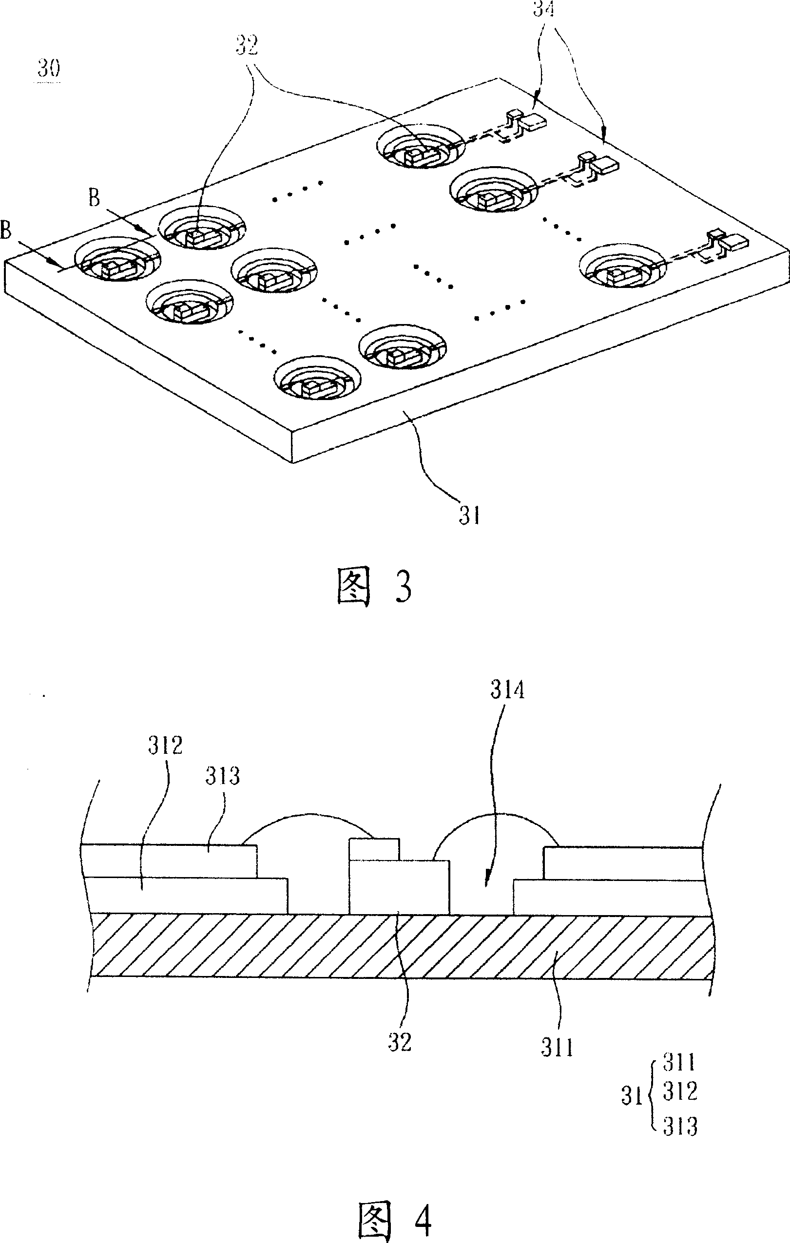
[0090] Please refer to FIG. 3 , which is a three-dimensional schematic view of the LED module according to the first embodiment of the present invention. The LED module 30 includes a circuit substrate 31 and a plurality of LED chips 32 . It should be noted that the number and arrangement of the LED chips 32 in the LED module 30 are not limited. In the present embodiment, the LED dies 32 are arranged in an array as an example for illustration. Of course, each LED die 32 may also be arranged in a straight line.
[0091] Please refer to FIG. 3 and FIG. 4 at the same time, wherein FIG. 4 is a schematic cross-sectional view of the light-emitting diode module according to the first embodiment of the present invention along the section line B-B in FIG. link relationship. The circuit substrate 31 sequentially includes a metal layer 311, a first dielectric...
no. 2 example
[0104] Next, please refer to FIG. 11 to FIG. 16 to illustrate the second embodiment of the LED module of the present invention.
[0105] Please refer to FIG. 11 , which is a schematic view of the LED module according to the second embodiment of the present invention. The LED module 40 includes a circuit substrate 41 and a plurality of LED elements 42 . Wherein, the circuit substrate 41 has the same technical features and functions as the circuit substrate 31 in the first embodiment, so it will not be repeated here.
[0106] The LED module 40 can further include a driving circuit 44 , which is disposed on the circuit substrate 41 and electrically connected to each LED element 42 to drive the LED elements 42 . Wherein, the driving circuit 44 has the same technical features and functions as the driving circuit 34 in the first embodiment, so it will not be repeated here.
[0107] Please refer to FIG. 11 and FIG. 12 at the same time. FIG. 12 is a schematic cross-sectional view of...
PUM
 Abstract
Description
Claims
Application Information