
Cutting creep instrument

A creep meter and shear box technology, applied in the field of geotechnical engineering, can solve the problems of large volume, deviation of test data, large loading error, etc., and achieve the effects of good mechanism flexibility, high test accuracy and stable work.

Inactive Publication Date: 2008-01-16
CHANGAN UNIV
View PDF0 Cites 24 Cited by
  • Summary
  • Abstract
  • Description
  • Claims
  • Application Information

AI Technical Summary

Problems solved by technology

At present, the rheometers used in China generally use long lever mechanisms to apply vertical and horizontal loads. However, the use of lever mechanisms to apply loads has the following defects: (1) The size of the shear box of shear instruments commonly used in China is too small , the area is generally 30cm 2 , when the soil sample is sheared, it starts from the edge of the sample, and the circular box forms an obvious stress concentration phenomenon at the edge at the beginning, and the shear stress is the largest near the action point of the shear box. During the whole shearing process, There is always the problem of uneven shear stress distribution; (2) Once the soil sample is deformed, the lever will tilt, and the direction of the vertical force will change due to the tilt of the lever. The force F applied in the experiment v is getting bigger and bigger, the angle between the lever and the horizontal direction is getting bigger and bigger, F v It is not always perpendicular to the shear plane, but has an included angle with the vertical direction. With the improvement of the experimental accuracy requirements, the loading error is also increasing, resulting in a large deviation of the experimental data. The experiment proves that, f v When not vertical, the internal friction angle and cohesion obtained are greater than F v The value when vertical; (3) The leverage is applied in both directions, which makes the equipment bulky. Since the length of the lever cannot be too long, the loading value is limited, and the load cannot reach the actual force of the sample.

Method used


Image

  • Cutting creep instrument

Examples


Embodiment Construction

[0009] The present invention will be further described below in conjunction with the accompanying drawings.

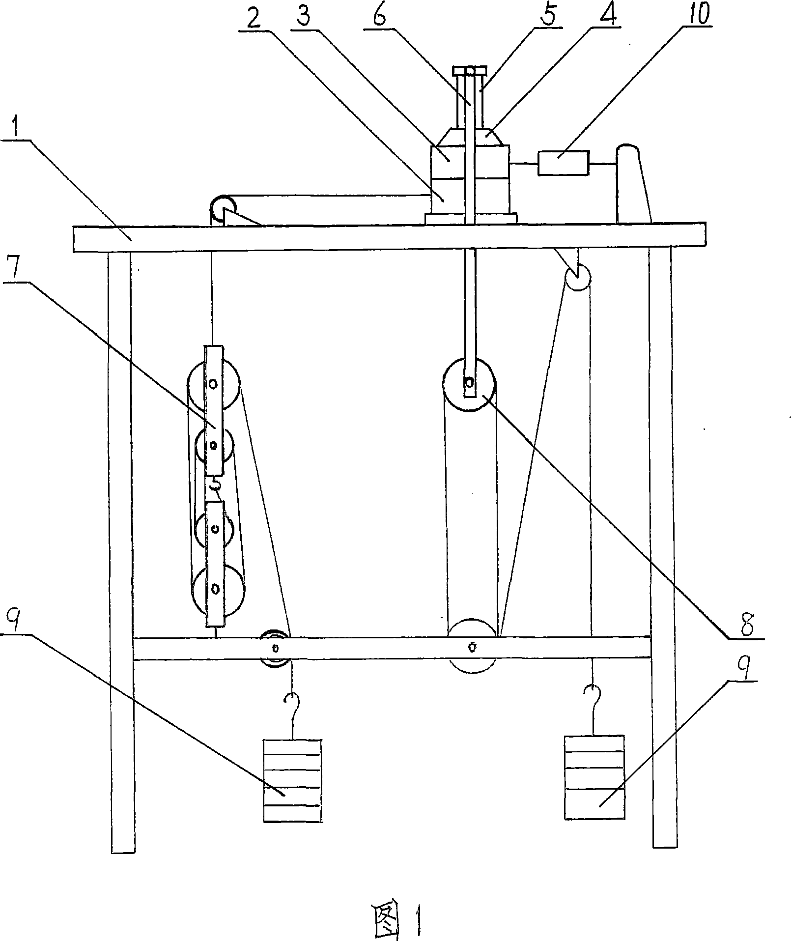
[0010] As shown in Fig. 1, the present invention comprises test bench 1, is positioned at test bench 1 and is provided with the shear box that is made up of lower shear box 2 and upper shear box 3, and the top of described shear box is provided with pressure-bearing cover 4. A pressure sensor 5 is provided on the pressure-bearing cover 4, and one side of the upper shear box 3 is connected to the tension sensor 10; the pressure sensor 5 is connected to the vertical pressure loading pulley block 8 through the force transmission frame 6; the lower shear box 2 The traction rope is connected with the horizontal shear force loading pulley block 7;

[0011] The shear box is square.

[0012] The vertical pressure loading pulley set 8 , the horizontal shear loading pulley set 7 and the weight 9 are all arranged under the test bench 1 .

[0013] Both the vertical pressure load...


PUM


Abstract

The invention discloses a shear creep tester which comprises a testing bench, a shear box arranged on the testing bench and formed by lower and upper shear box portions, a bearing cover arranged on the top of the shear box, a pressure sensor arranged on the bearing cover, and a tension sensor connected with one side of the upper shear box portion. The pressure sensor is connected with a vertical pressure loading pulley block by a transmission frame. The lower shear box portion is connected with a horizontal shear loading pulley block by a traction rope. The moving end of the traction rope, bridging the vertical pressure loading pulley block and the horizontal shear loading pulley block, is connected with a counterweight. The invention has the advantages of reasonable design, simple, flexible and practical structure of pulley block, high test accuracy, stable performance, and convenient operation.

Description

technical field [0001] The invention relates to a device for measuring creep properties of soil in the field of geotechnical engineering, in particular to a shear creep meter. Background technique [0002] Under ideal conditions, the soil specimen is under the vertical force, that is, the normal stress F v and the horizontal force that is the shear stress F b Destroyed under the joint action, where F v The force must be vertical, and the ideal failure mode of the specimen should be a parallel displacement of one side relative to the other. At present, the rheometers used in China generally use long lever mechanisms to apply vertical and horizontal loads. However, the use of lever mechanisms to apply loads has the following defects: (1) The size of the shear box of shear instruments commonly used in China is too small , the area is generally 30cm 2 , when the soil sample is sheared, it starts from the edge of the sample, and the circular box forms an obvious stress concen...

Claims


Application Information

Patent Timeline
IPC IPC(8): G01N3/24
Inventor 李同录蔺晓燕李萍龙建辉张常亮赵成潘春雷章健
Owner CHANGAN UNIV
Learn More