Medical image window parameter self-adaptive regulation method

A technology of self-adaptive adjustment and window parameters, applied in the field of medical image display processing, can solve problems such as difficulties and inability to automatically calculate window parameters, and achieve strong robustness and good display effects

Inactive Publication Date: 2008-01-16
NINGBO UNIV
View PDF0 Cites 35 Cited by
  • Summary
  • Abstract
  • Description
  • Claims
  • Application Information

AI Technical Summary

Problems solved by technology

[0003] One of the problems faced by the window adjustment technology in displaying medical images is whether the displayed medical images can fully highlight the key information useful for diagnosis, such as soft tissue, bone, brain tissue, lung, abdomen, etc. in the image
In practical applications, due to the large number of manufacturers and equipment models of medical imaging equipment, in many cases, the image file does not indi...

Method used


Image

  • Medical image window parameter self-adaptive regulation method
  • Medical image window parameter self-adaptive regulation method
  • Medical image window parameter self-adaptive regulation method

Examples


Embodiment 1

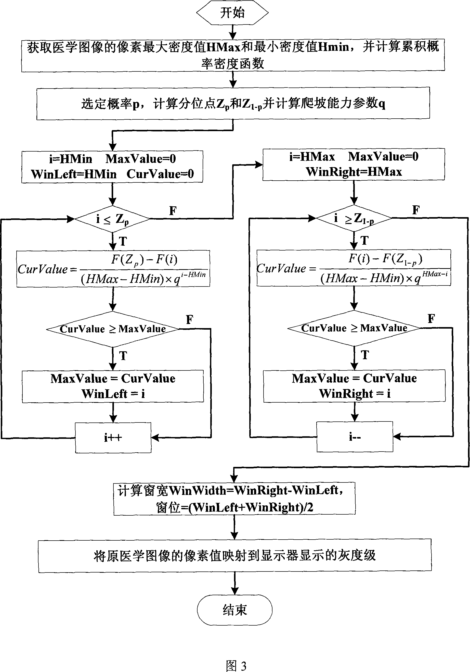
[0046] Embodiment 1: The left lower limb digital image, the pixel value range of the original image is [0,1024], and the following operations are performed on the left lower limb digital original image according to the specific implementation flowchart shown in FIG. 3:

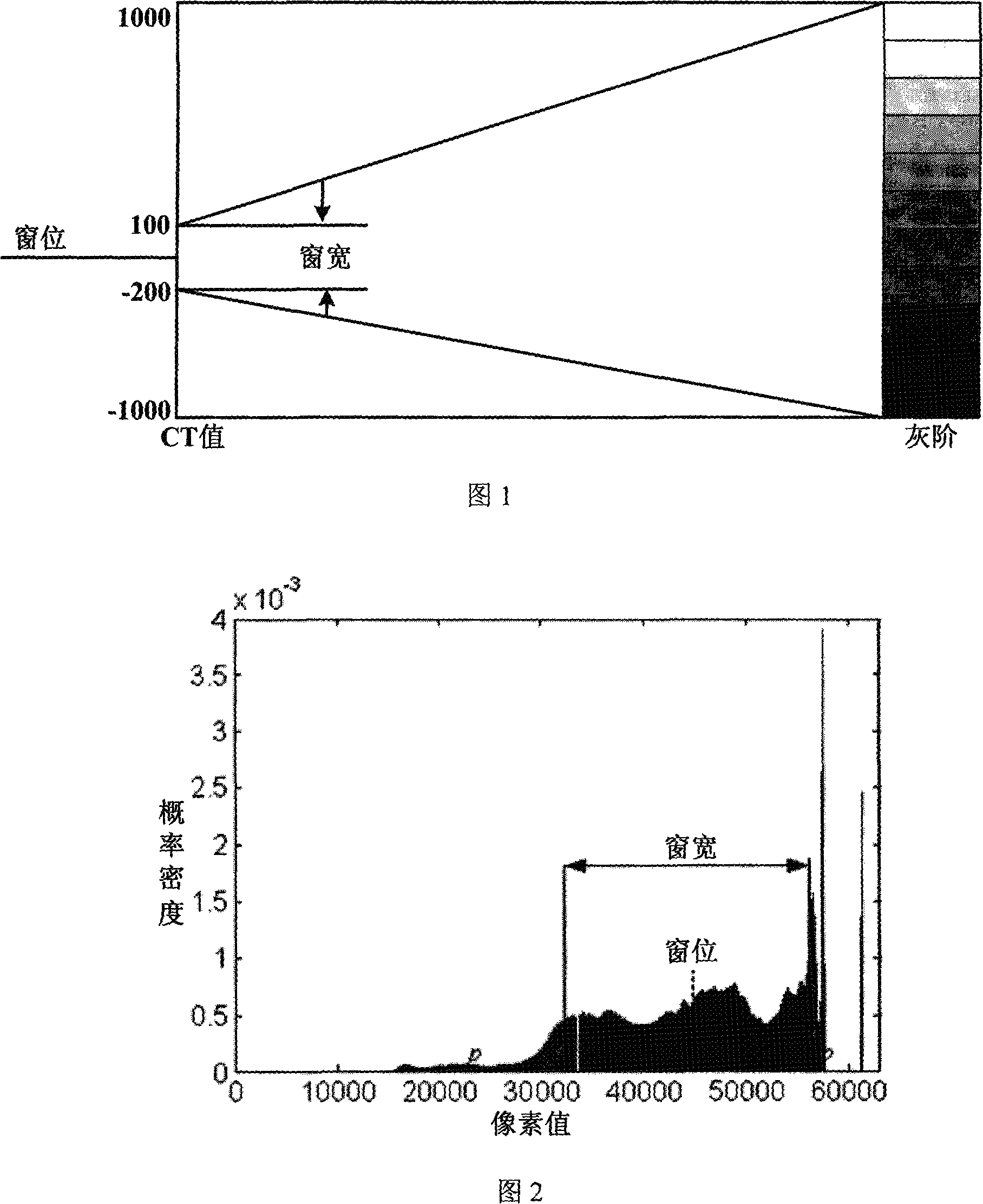
[0047] In the process of medical image imaging, tissue information important for diagnosis is often represented by a relatively large number of pixels, and for a certain tissue part, there is a certain value interval, which basically does not depend on equipment and imaging software. In this way, in the pixel value probability density function f(x) of the image, the interval representing the key organization will have a higher peak, and the two sides of this interval are relatively flat. The search for the optimal window is actually to find the key organization. The interval of, that is, the overall part of the image histogram, the present invention mainly locates the main part of the image histogram according to ...

Embodiment 2

[0056] The second embodiment: CR image of the fracture of the left upper limb forearm. The pixel value range of the original image is [1912, 3389]. The operation performed on it according to the specific implementation flowchart shown in Figure 3 is the same as that of the first embodiment. The difference lies in this The maximum density value of the image pixels of the embodiment is 3389 and the minimum density value is 1912. The window width WinWidth=956 and the window level WinLevel=2890 are finally obtained through calculation, as shown in FIG. 7a.

[0057]The following compares the display effect of the CR image of the fracture CR image of the left upper limb forearm in the present embodiment by truncating the two ends of a certain probability interval according to the histogram and the display effect of the method of the present invention. Figure 6a shows the probability of truncating both ends according to the histogram. The image histogram and window position schematic dia...


PUM


Abstract

The invention discloses a self-adapting adjustment method for medical image window parameters. The method calculates the left boundary and right boundary of the window according to the accumulated probability intensity function of digital medical images, fractile of probability p, fractile of probability 1-p and climbing parameter q, so that position boundaries at major body of the image column diagram can be used to suitably determine the window parameter width and position of medical images, and then reflects the pixel value of digital medical images to the grey area in the grey stage range of the display. The invention has the advantages that through the automatic calculation of the optimum window width parameters through medical image information, users can obtain clear and satisfactory display images, thus having the high robustness; the window determined by the invention makes full use of the display gray stage of display, giving prominence to organization information useful for clinical diagnosis; the test and long-time clinical application prove that the invention is suitable for most of medical images and has the good display effect.

Description

Technical field [0001] The invention relates to a medical image display processing method, in particular to an adaptive adjustment method of medical image window parameters. Background technique [0002] The digital medical image adopts the DICOM (Digital Imaging and Communication of Medicine) standard format. The image data represents the density information of human tissue collected by the medical imaging device. The data of each pixel on the image generally has 8 bits-16 bits. The current digital medical images are generally displayed in the form of grayscale images on the display screen, and most displays often only support 8bits grayscale display, so only part of the information of the digital medical images can be displayed. In view of this, the display of medical images usually adopts a technique called window adjustment (also called window width and window level), that is, only a part of the pixel value range of the original medical image is mapped to the gray scale that ...

Claims


Application Information

Patent Timeline
IPC IPC(8): G06T5/00A61B19/00G09G5/00
Inventor 李均利魏平陈刚
Owner NINGBO UNIV
Why Eureka
Try Eureka