Ultrasonic motor closed loop control circuit

A closed-loop control circuit, ultrasonic motor technology, applied in the direction of generators/motors, piezoelectric effect/electrostrictive or magnetostrictive motors, electrical components, etc., can solve the problems of asymmetrical forward and reverse rotation of ultrasonic motors

Inactive Publication Date: 2008-01-16
HENAN UNIV OF SCI & TECH
View PDF0 Cites 22 Cited by
  • Summary
  • Abstract
  • Description
  • Claims
  • Application Information

AI Technical Summary

Problems solved by technology

[0010] The purpose of the present invention is to provide a simple and practical ultrasonic motor closed-loop contro

Method used


Image

  • Ultrasonic motor closed loop control circuit
  • Ultrasonic motor closed loop control circuit
  • Ultrasonic motor closed loop control circuit

Examples


Embodiment 1

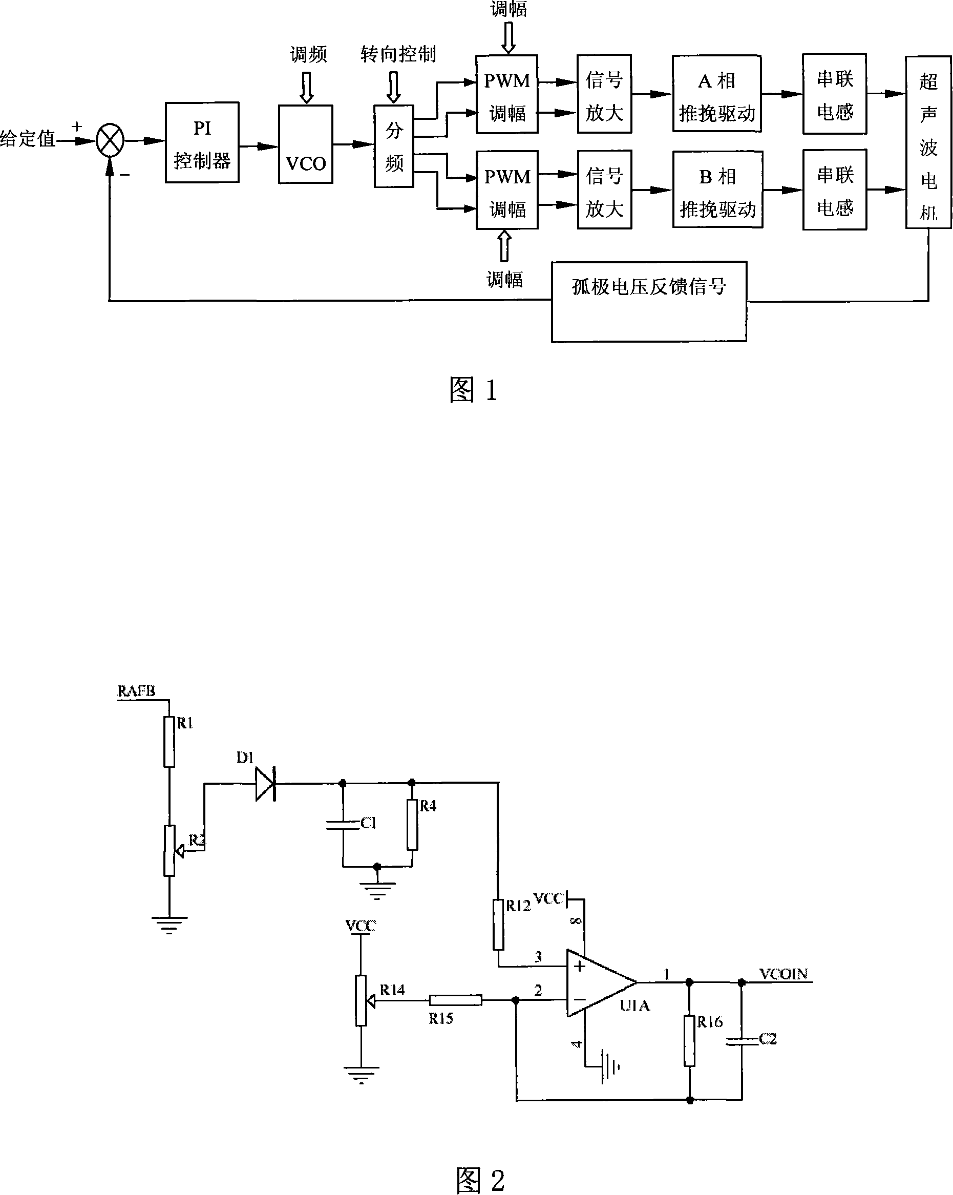
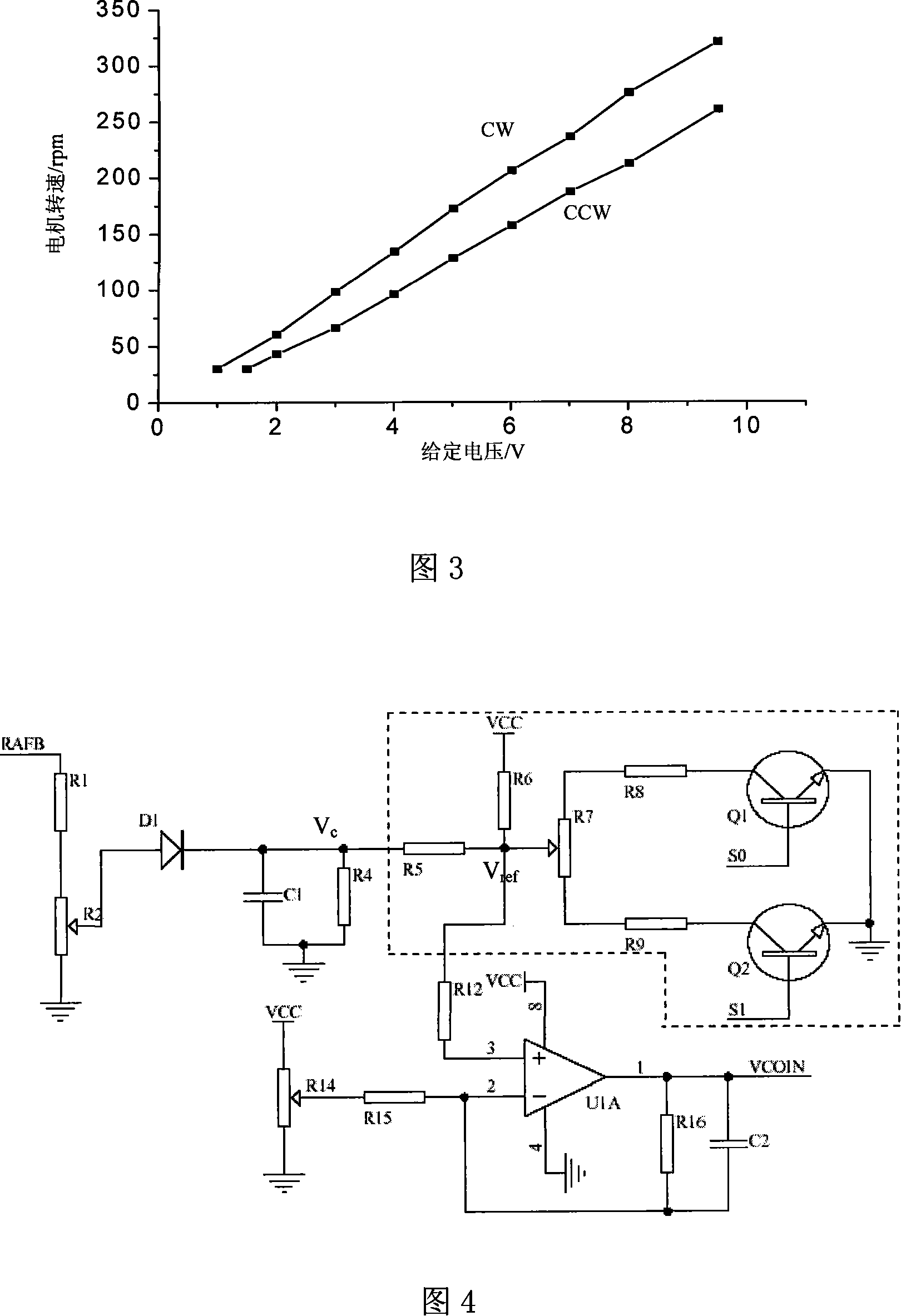
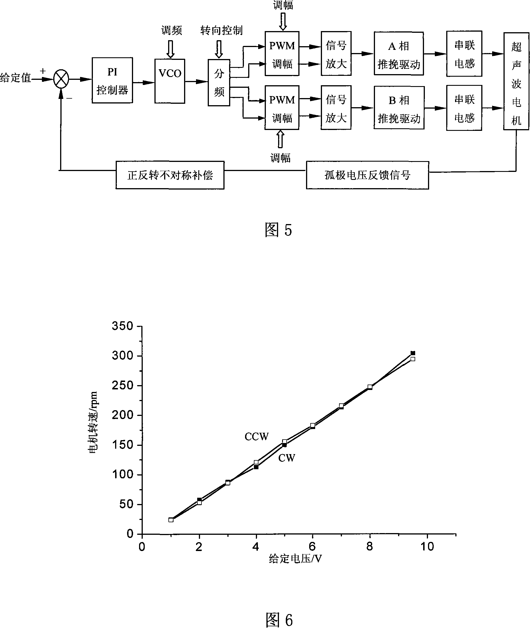
[0026] The lone pole piezoelectric ceramic sheet set on the stator of the ultrasonic motor is rectified and filtered by the feedback signal processing circuit, then processed by a forward and reverse compensation circuit, and finally sent to the frequency controller; the circuit of the forward and reverse asymmetric compensation circuit of the ultrasonic motor The connection diagram is shown in Figure 4. The negative input terminal of the operational amplifier U1A in the frequency controller is connected in series with the adjustable terminal of the potentiometer R14 through the voltage dividing resistor R15, and the two ends of the potentiometer R14 are respectively connected between the power supply VCC and the ground. The given signal value of the negative input terminal of the operational amplifier U1A is set by adjusting the potentiometer R14; the lone pole voltage feedback signal RAFB is divided by the upper part of the resistor R1 and the potentiometer R2 in series, and t...

Embodiment 2

[0031] The forward and reverse asymmetry compensation circuit of the ultrasonic motor in this embodiment is shown in Figure 7. The output voltage RAFB of the lone-pole piezoelectric ceramic plate set on the stator of the ultrasonic motor is firstly rectified and filtered by the feedback signal processing circuit, and then sent to the frequency controller The positive input terminal of the operational amplifier U1A; the feedback signal rectification and filtering circuit are the same as those in Embodiment 1, and will not be repeated here.

[0032] A positive and negative compensation circuit is set between the negative input terminal of the operational amplifier and the adjustable terminal of the potentiometer R14 for setting the given signal, and the circuit setting of the compensation circuit is the same as that of Embodiment 1, where the difference is: the resistance R5 is set to the given signal The adjustable terminal of the signal potentiometer R14 is connected in series,...


PUM


Abstract

The invention relates to a closed loop control circuit for ultrasonic motor. A positive inversion unbalanced compensation circuit for ultrasonic motor is equipped between the output terminal of the isolated electrode voltage and the frequency controller. According to that the control error of the frequency controller is equal to the given value minus isolated electrode voltage feedback value, adjusting the feedback value or the given signal value to make the control error of the frequency controller close when the motor is in positive inversion can change output frequency of the frequency controller, making the ultrasonic motor have close rotational speed in positive inversion under control of subsequent circuit. The compensation circuit comprises a rheostat with the two ends respectively connected with a gating branch. The adjustable terminal of the rheostat is connected with the output terminal of the rectifier filter processing circuit. A power supply is series-connected with the adjustable terminal of the rheostat via a DC bias resistor, and then connected with the positive input terminal of the operational amplifier, controlling the corresponding gating branch and conducting voltage dividing by positive inversion control signal. The operational amplifier in frequency controller can figure out different signal value, making frequency controller output close control signal.

Description

technical field [0001] The invention relates to an ultrasonic motor, in particular to the technical field of drive control of an ultrasonic motor. Background technique [0002] Ultrasonic motor is a new type of micro motor, which has a working principle and structure different from traditional motors. Compared with traditional motors, ultrasonic motors have simple structure, no coils, light weight, flexible shape, no noise, and no magnetic field radiation. These advantages make ultrasonic motors widely used in high-end motion control fields such as aerospace, precision processing equipment, medical instruments, and bioengineering equipment, as well as general motion control fields such as household appliances and automotive electronics. All have broad application prospects. [0003] Fig. 1 is the structural block diagram of the closed-loop control circuit of the ultrasonic motor in the prior art, in the figure frequency controller (PI controller) carries out operation accor...

Claims


Application Information

Patent Timeline
IPC IPC(8): H02N2/14
Inventor 史敬灼周鲁英刘兆魁侯义铭肖隽亚
Owner HENAN UNIV OF SCI & TECH
Why Eureka
Try Eureka