Gas light-emitting diode

A light-emitting diode and gas technology, which is applied in the field of gas light-emitting diodes, can solve problems such as difficulty in increasing the power

Inactive Publication Date: 2012-05-23
福州恊特来照明有限公司 +1
View PDF5 Cites 0 Cited by
  • Summary
  • Abstract
  • Description
  • Claims
  • Application Information

AI Technical Summary

Problems solved by technology

In order to maintain the discharge at both ends, the application of electronic powder can only be limited to a very short range at both ends of the filament. The life of the lamp is about 2000 hours, and the power is difficult to increase.

Method used


Image

  • Gas light-emitting diode
  • Gas light-emitting diode
  • Gas light-emitting diode

Examples


Embodiment 1

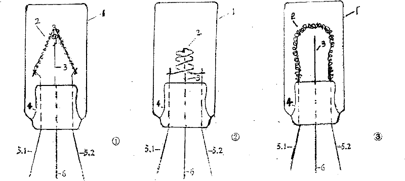
[0011] Embodiment 1 image 3 - In ①: the cathode spiral 2 is a Λ (rumda) structure; the diameter of the anode rod 3 is 0.6-0.9 mm.

Embodiment 2

[0012] Example two attached image 3 - In ②, the cathode spiral 2 is a Θ (Stether) structure with an inner diameter of 6 mm, a spiral length of 9 mm, and 3 to 5 turns of the spiral; the diameter of the anode rod is 0.6 to 0.9 mm.

Embodiment 3

[0013] Embodiment Three Attachment image 3 — In ③ middle: the cathode spiral 2 is an omega (omega) structure; the diameter of the anode rod 3 is 0.6-0.9 mm.

[0014] The anode rod, the cathode spiral and the core post form the wick; the wick and the glass envelope are then sealed to the GLED of the invention.

[0015] will attach image 3 - The cathode outer guide wire 5.1 and 5.2 in ①②③ are combined and then connected to the negative pole of the power supply, and the anode outer guide wire 6 is connected to the positive pole of the power supply. The cathode and anode in the lamp form a positive corona discharge system and a hollow cathode discharge system.

[0016] Beneficial effect

[0017] 1. Positive resistance discharge There are many forms of discharge. The current technology commonly used is positive column discharge; positive column discharge is based on parallel electrodes and a uniform electric field, showing negative resistance characteristics.

[0018] The dis...


PUM


Abstract

The invention discloses a gas LED, that is, a GLED, which comprises a glass shell, a stem, an anode pole and a cathode spire. The invention is characterized in that: the cathode spire is provided with an internal cavity structure; the anode pole is positioned at the center of a cathode internal cavity of the spire; a cathode is connected to the negative pole of a power source; an anode is connected to the positive pole of the power source. After the power source is switched on, the anode and cathode in a glass tube comprise a positive halo discharge filled in the internal cavity of electric pole as well as a hollow cathode discharge system. Therefore, the invention is able to effectively enhance the radiation efficiency of ultraviolet radiation after being made into an ultraviolet sterilization lamp and is able to realize high lumen and light effect after being made into a fluorescent lamp.

Description

technical field [0001] LED refers to light-emitting diodes, and LEDs have inorganic light-emitting diodes, namely ILEDs; organic light-emitting diodes, namely OLEDs; ILEDs and OLEDs are collectively referred to as solid light-emitting diodes. The present invention refers to gas light emitting diodes, ie GLEDs. Background technique [0002] People always hope to use fluorescent lamps like incandescent lamps, so there are patterns of making straight tube fluorescent lamps into H, U, spiral and other shapes; [0003] figure 1 Shown is the small discharge lamp disclosed in Japanese Patent No. 63-234976, in which the anode and the cathode are arranged in close proximity and parallel to each other in structure. This kind of wick will cause glow discharge arc short circuit, and the cathode decomposition is difficult to complete; a uniform electric field is formed in the discharge space, so that the discharge falls into the positive column discharge mode, the electrode potential d...

Claims


Application Information

Patent Timeline
Patent Type & Authority Patents(China)
IPC IPC(8): H01J61/04H01J61/35
Inventor 陈寿峦
Owner 福州恊特来照明有限公司
Why Eureka
Try Eureka