LCD device and scanning method

A technology of liquid crystal display device and scanning method, which is applied in the direction of static indicators, instruments, etc., to achieve the effect of solving light leakage and avoiding discontinuity

Active Publication Date: 2008-01-30
DYNASCAN TECH
View PDF1 Cites 33 Cited by
  • Summary
  • Abstract
  • Description
  • Claims
  • Application Information

AI Technical Summary

Problems solved by technology

[0009] The purpose of the invention is to solve the problem o

Method used


Image

  • LCD device and scanning method
  • LCD device and scanning method
  • LCD device and scanning method

Examples


Embodiment Construction

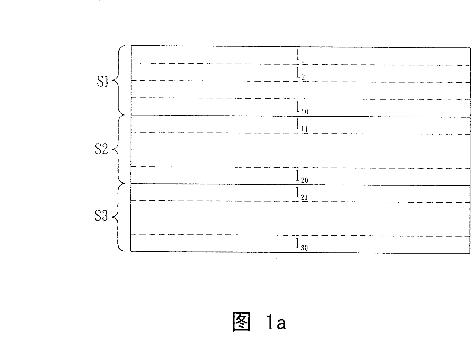
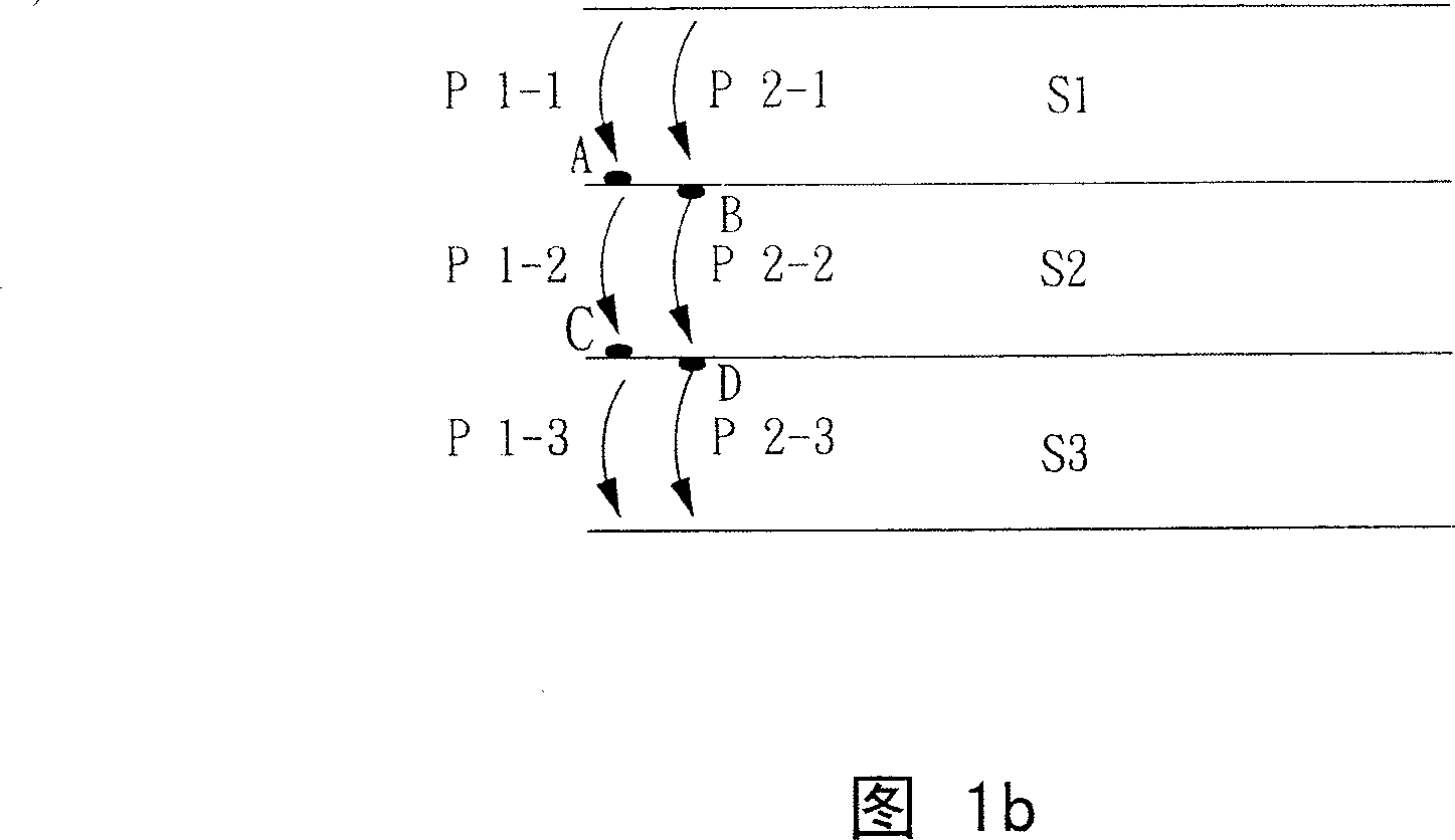
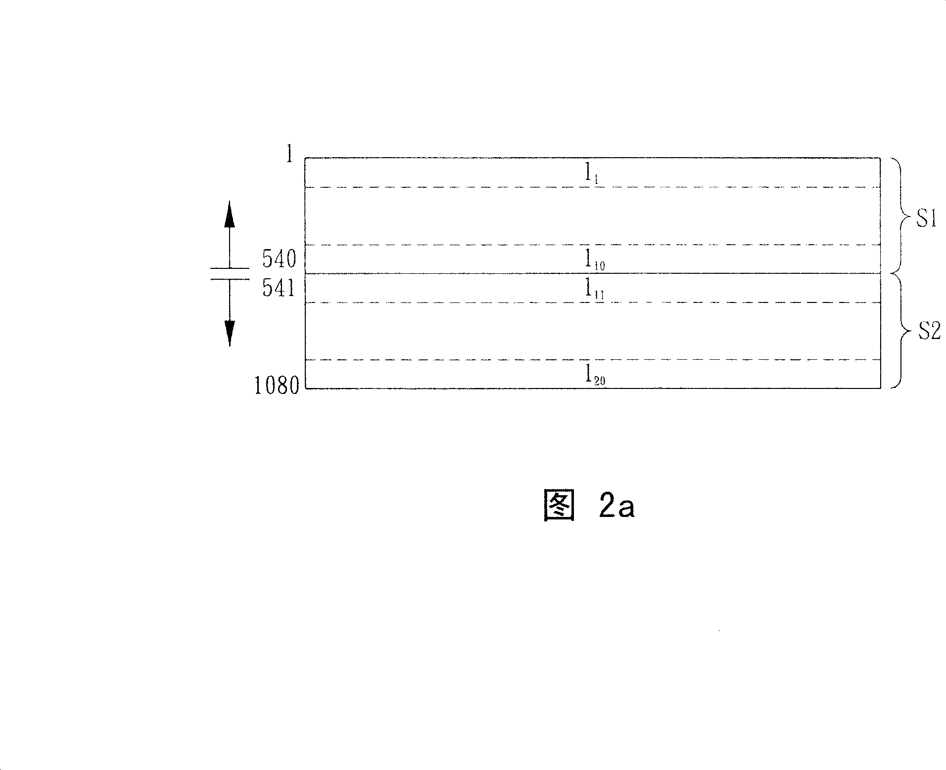
[0033] As mentioned above, although the present invention aims to solve the problems of the known liquid crystal display devices with achromatic filters, the liquid crystal display devices and methods proposed in the present invention include and are applicable to both achromatic filters and chromatic ones. filter on the LCD device. The following description first cuts in from several more complex embodiments of the present invention. These embodiments are all achromatic filters, with red, green and blue LEDs as the backlight source, and the screen is divided into three colors according to red, green and blue. Three-color separation is a liquid crystal display device in which sub-pictures are displayed sequentially in time division. Once the spirit of the invention is understood from these more complex embodiments, the colored filter embodiments of the invention can be understood without further explanation. Furthermore, the spirit of the present invention does not limit whet...


PUM


Abstract

The invention provides a liquid crystal display device as well as a relative scanning method. One implementation example of the invention is a colorless filter, and a liquid crystal display device which uses a red light emitting diode, a green light emitting diode and a blue light emitting diode as back light source, as well as a relative scanning method. The device is characterized in that a panel scanning line is divided into a plurality of scanning areas in the direction parallel to the scanning line, and each scanning area is further divided into at least one small zone. A back light module provides a corresponding group of light emitting diodes behind each small zone, and each group of light emitting diodes comprises a red light emitting diode, a green light emitting diode and a blue light emitting diode in proper sequence; wherein, when a color separated sub-picture is displayed, the scanning order of neighbor scanning areas is in the direction of facing a juncture or in the opposite direction of leaving the juncture. When the scanning of a small zone is finished, and after liquid crystal molecules finish the reaction, the corresponding group of light emitting diodes behind the small zone is lightened, thus avoiding the discontinuous phenomenon of dynamic pictures.

Description

technical field [0001] The present invention relates to a liquid crystal display device, in particular to a liquid crystal display device and a scanning method thereof which divide scanning areas and scan adjacent scanning areas in opposite directions. Background technique [0002] The currently known color liquid crystal display (liquid crystal display, LCD) mainly uses a color filter (color filter), so that the light emitted from the cold cathode fluorescent light (CCFL) tube of the backlight module (backlight module) White light passes through the liquid crystal panel and the processing of color filters to present a colorful picture. Color filters are the most costly among LCD components. Taking the 14.1-inch TFT-LCD panels used in notebook computers as an example, color filters account for about 28% of all material costs, which is higher than that of backlight modules (18%) and Purchase cost of other components. [0003] With the progress of light emitting diode (light...

Claims


Application Information

Patent Timeline
IPC IPC(8): G09G3/36G09G3/20G02F1/133
Inventor 王遵义
Owner DYNASCAN TECH
Why Eureka
Try Eureka