Transverse shearing interferometer agglutination checking method

A technology of transverse shearing and detection method, which is applied in the field of gluing detection of transverse shearing interferometer, can solve the problem that the transverse shearing amount of transverse shearing interferometer is difficult to control accurately, and achieve convenient adjustment and calibration of optical path and ensure accuracy , Improve the effect of control accuracy

Inactive Publication Date: 2008-02-13
XI'AN INST OF OPTICS & FINE MECHANICS - CHINESE ACAD OF SCI
View PDF0 Cites 16 Cited by
  • Summary
  • Abstract
  • Description
  • Claims
  • Application Information

AI Technical Summary

Problems solved by technology

[0006] The purpose of the present invention is to provide a glue detection method of a transverse shear interferometer, to solve the technical problem that the transverse shear amount of the transverse shear interferometer in the background art is difficult to accurately control

Method used


Image

  • Transverse shearing interferometer agglutination checking method
  • Transverse shearing interferometer agglutination checking method
  • Transverse shearing interferometer agglutination checking method

Examples


Embodiment Construction

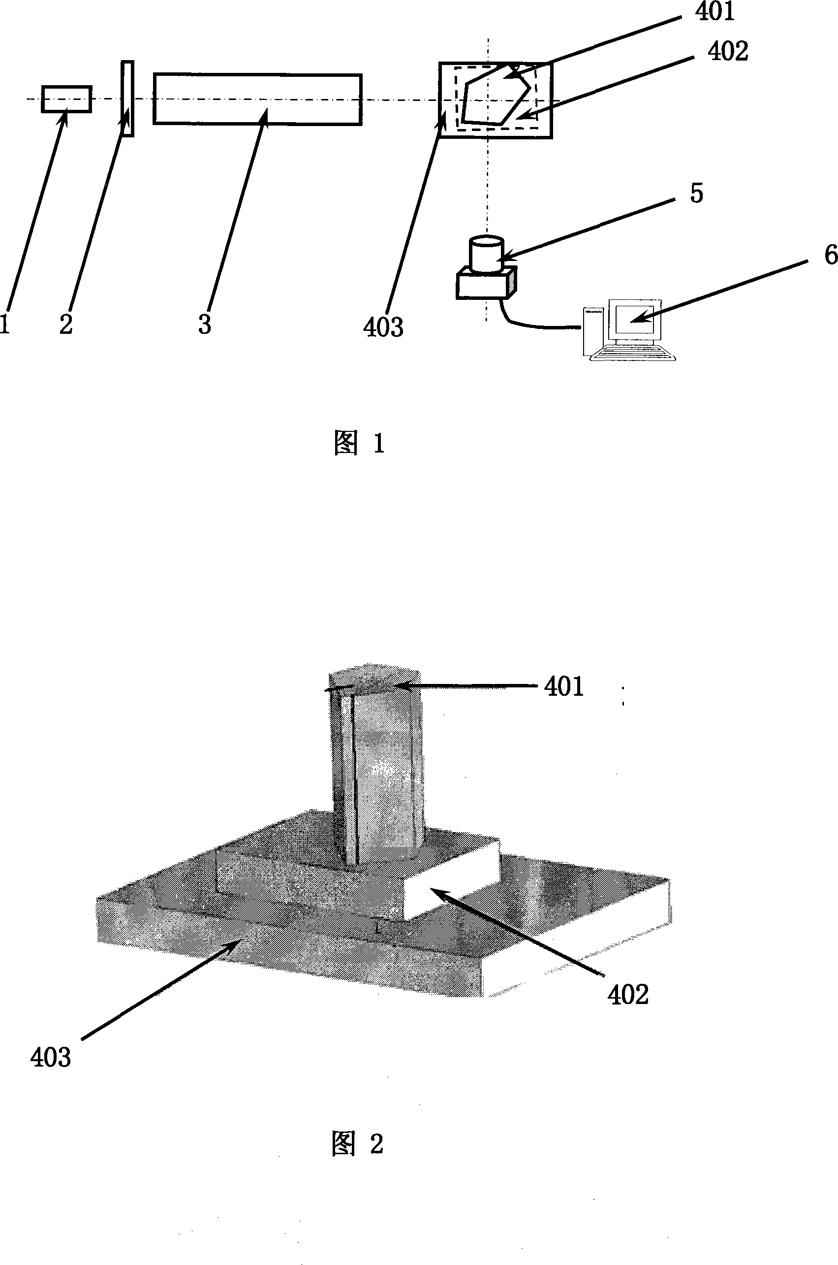
[0039] The principle of the invention: the gas laser has the characteristics of high collimation and high monochromaticity. The laser output from the gas laser enters the transverse shearing interferometer after beam expansion, and quasi-monochromatic interference fringes with high contrast can be obtained. For the convenience of fringe reading, each interference fringe is collected with no less than 5 CCD pixels.

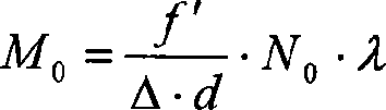
[0040] Suppose: the laser wavelength is λ, the focal length of the digital camera is f′, the CCD pixel size is d, and the number of interference fringes is N 0 , N 0 The number of CCD pixels occupied by each interference fringe is M 0 ;

[0041] Then the shear amount is calculated by the formula: Δ = f ′ M 0 · d · N 0 · λ , ...


PUM


Abstract

A scuffing detection method for a lateral shearing interferometer is provided. The lateral shearing interferometer to be scuffed is coated evenly with photosensitive glues and is vertically put on a high precision optical plate of a precision adjusting platform. The laser light output by a laser forms into even parallel light on the lateral shearing interferometer to be scuffed. Interference fringes formed on the send out end of the lateral shearing interferometer to be scuffed are received by a digital camera and are displayed in real time on a computer. The CCD pixel number M0 of the digital camera occupied by N0 interference fringes is calculated. Two prisms are moved slightly to read CCD pixel number M of the digital camera occupied by N0 interference fringes. When the CCD pixel number M becomes to be M0, the two prisms are set not to move. The two scuffed prisms are solidified. The invention solves a technical problem in background technology that the lateral shearing amount of the lateral shearing interferometer is hard to be precisely controlled. The error of the lateral shearing amount of the invention can be controlled within 1%.

Description

technical field [0001] The invention relates to a method for gluing and detecting a transverse shear interferometer. Background technique [0002] The transverse shearing interferometer is the core component of various spatially modulated interferometric spectrometers and interferometric imaging spectrometers. The transverse shearing amount of the transverse shearing interferometer is determined by the translucency and incomplete symmetry of the glued surfaces of the two prisms. produced. Since the transverse shear value of the transverse shear interferometer determines the maximum optical path difference OPD of the interferometer max , and the maximum optical path difference determines the spectral resolution δσ, [0003] δσ = 1 2 · OP D max [0004] When the actual gluing and detection transverse shear is less ...

Claims


Application Information

Patent Timeline
Patent Type & Authority Applications(China)
IPC IPC(8): G01B9/02G02B7/18
Inventor 赵葆常杨建峰薛彬乔卫东陈立武贺应红常凌颖张健
Owner XI'AN INST OF OPTICS & FINE MECHANICS - CHINESE ACAD OF SCI
Why Eureka
Try Eureka