Image border scanning system and method

A boundary scan and imaging technology, applied in image enhancement, image analysis, image data processing, etc., can solve problems such as heavy workload, poor repeatability, and large accidental errors, and achieve the effect of improving work quality and efficiency

Inactive Publication Date: 2008-02-13
HONG FU JIN PRECISION IND (SHENZHEN) CO LTD +1
View PDF0 Cites 18 Cited by
  • Summary
  • Abstract
  • Description
  • Claims
  • Application Information

AI Technical Summary

Problems solved by technology

The programming is manual programming, which has a large workload, and the occasional error is relatively large, and the repeatability is poor.

Method used


Image

  • Image border scanning system and method
  • Image border scanning system and method
  • Image border scanning system and method

Examples


Embodiment Construction

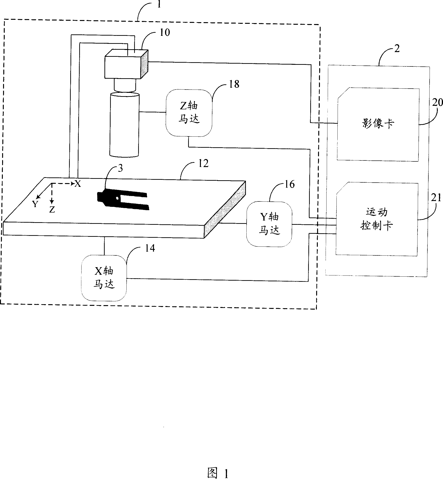
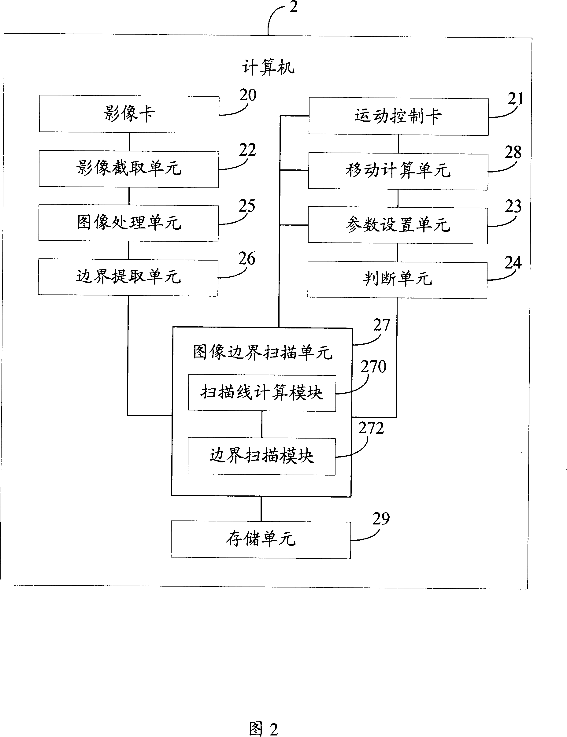
[0016] As shown in FIG. 1 , it is a hardware architecture diagram of a preferred embodiment of the image boundary scan system of the present invention. The system includes an image measuring machine 1 and a computer 2 for automatically scanning at least one workpiece 3 . The image measuring machine 1 includes a charge coupled device (CCD) sensor 10 , a worktable 12 , an X-axis motor 14 , a Y-axis motor 16 and a Z-axis motor 18 . The computer 2 includes a video card 20 and a motion control card 21 .

[0017] Wherein, the CCD sensor 10 includes a CCD and a lens, and the CCD sensor 10 is connected with the image card 20 for acquiring the image of the workpiece 3 placed on the workbench 12 . The CCD sensor 10 has a fixed shooting range. When its fixed shooting range is less than the size of the workpiece 3, the motion control card 21 controls the movement of the X-axis motor 14 and the Y-axis motor 16, and then changes the direction of the worktable 12 in the X-axis and Y-axis d...


PUM


Abstract

The invention provides an image boundary scan method, which makes use of an image boundary scan system to scan the image boundary of a work piece. The system includes a computer and an image measurement machine station. The image measurement machine station includes a charge coupled device sensor, a working platform for carrying the work piece and a motor. The method includes steps mentioned below. The image of the work piece is intercepted through the charge coupled device sensor. The computer is equipped with parameters of the image boundary scanning. The image process is implemented on the image and a starting point is chosen from the processed image. A boundary point which is nearest to the starting point is found along the starting point. The boundary contour near the boundary point is extracted. A recursive method is used to search for other boundary points on the boundary contour. The boundary points are searched precisely on the processed image according to the parameters of the image boundary scanning and are regarded as scanning points for boundary scanning.

Description

technical field [0001] The invention relates to an image boundary scanning system and method. technical background [0002] Measurement is an important link in the production process, and it is closely related to the quality of the product. For the measurement of Ball Grid Array (BGA), three-dimensional curved surface (3D) and transparent parts, the traditional method is to use Charge Coupled Device (CCD) and contact measurement methods. The BGA, 3D and workpieces can also be scanned by using an image measuring machine equipped with a CCD, and the pictures taken by the CCD are converted into digital files for storage in a computer. [0003] In the process of measuring the workpiece by the image measuring machine, the CCD is required to capture the image of the workpiece to be scanned, and then program the image to be scanned. Due to the characteristic requirements of the CCD lens of the image measuring machine, the range of the workpiece image acquired at one time is limit...

Claims


Application Information

Patent Timeline
Patent Type & Authority Applications(China)
IPC IPC(8): G01B11/00G06K9/60
CPCG06T2207/30164G06T7/0004G06T7/0083G06T7/12
Inventor 张旨光孙小超蒋理
Owner HONG FU JIN PRECISION IND (SHENZHEN) CO LTD
Why Eureka
Try Eureka