Contaminator and purification process real-time monitoring and delaminated control and execution system

A technology of layered control and real-time monitoring, applied in electrical program control, comprehensive factory control, comprehensive factory control, etc., can solve problems such as aggravating environmental degradation, equipment waste, and enterprise stealing, achieve real-time data transmission, and improve interrupt execution. The effect of strength

Active Publication Date: 2008-02-13
SHANXI LIANHUA WEIYE TECH
View PDF0 Cites 2 Cited by
  • Summary
  • Abstract
  • Description
  • Claims
  • Application Information

AI Technical Summary

Problems solved by technology

[0002] The traditional manufacturing industry only pays attention to output and simple benefits, but largely ignores the historical mission of environmental protection. Many companies blindly pursue profits. In order to reduce costs, pollutant purification equipment is only opened when inspectors inspect it. They are closed as soon as people leave, and some do not even have purification equipment. In the late 1990s, online monitoring equipment for pollution sources appeared. These instruments can only monitor the sampled pollutants one-sidedly, and cannot reflect the status quo of the enterprise's sewage discharge well. and pollution control situation, enterprises still have serious illegal emissions, and the management department has no effective management methods and measures, which exacerbates the deterioration of the environment; in addition, the existing online monitoring industry of pollution sources only monitors but does not control, and cannot make use of Monitoring and control are carried out at the same time, and post-event control cannot effectively reduce the discharge of pollutants. After-event rectification makes unit purification facilities set up and not used, resulting in serious waste of equipment

Method used


Image

  • Contaminator and purification process real-time monitoring and delaminated control and execution system
  • Contaminator and purification process real-time monitoring and delaminated control and execution system
  • Contaminator and purification process real-time monitoring and delaminated control and execution system

Examples


Embodiment Construction

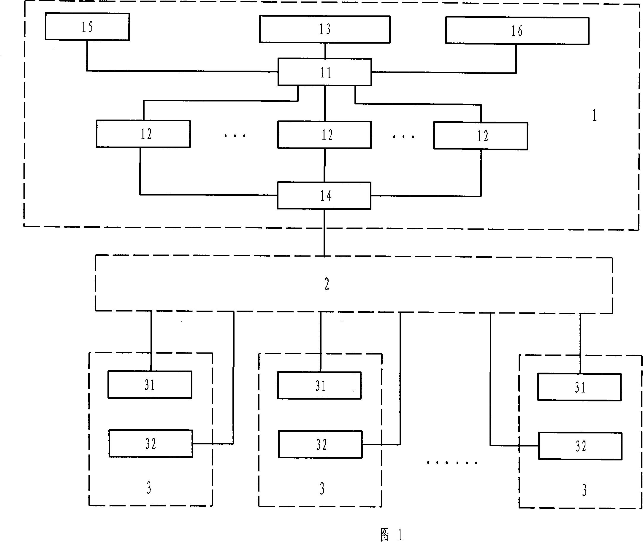
[0018] Figure 1 is a schematic diagram of the hardware system structure of the present invention; the figure mainly includes the core layer 1, the transmission layer 2, and the centralized control layer 3. It is composed of the core layer 1, the transmission layer 2 and the centralized control layer 3 from top to bottom, among which, The core layer 1 includes the master control server 11, the collection server 12, the database server 13, the central switch 14, the application workstation 15 and the geographic information system server 16. The transmission layer 2 includes transmission equipment and the network platform of the network operator, and the centralized control layer 3 includes The intelligent real-time monitoring box 31 and the intelligent hierarchical control box 32; the central switch 14 of the core layer 1 and the intelligent real-time monitoring box 31 of the centralized control layer 3 communicate through the transmission layer 2 to realize data collection and stor...


PUM


Abstract

The invention discloses a real-time monitoring and hierarchical control execution system for discharge and purification process of pollutants, specifically relating to the real-time monitoring and hierarchical control execution system for discharge and purification process of pollutants. A technical problem that needs to be solved is to provide the real-time monitoring and hierarchical control execution system for discharge and purification process of pollutants, thus, making the discharge and purification process of pollutants monitored and controlled. Different execution methods can be adopted according to the different discharge and purification level. The adopted proposal comprises a core layer, a transmission layer and a centralized control layer. The system consists of a core layer, a transmission layer and a centralized control layer from top to bottom. The core layer has relative serves to form an Ethernet net. The transmission layer comprises transmission equipment and a network platform for network operators. The centralized control layer comprises an intelligent real-time monitoring box and an intelligent layering control box. The invention can be widely applicable to the factories that discharge pollutants and purification factories, which illustrates a good prospect of application.

Description

Technical field [0001] The present invention is a real-time monitoring and hierarchical control execution system for pollutants and purification processes, and specifically relates to a real-time monitoring and hierarchical control execution system for pollutant discharge and purification processes. Background technique [0002] The traditional manufacturing industry only values ​​output and simple benefits, and largely ignores the historical mission of environmental protection. Many companies blindly pursue benefits. In order to reduce costs, pollutant purification equipment is only opened when inspectors are inspecting. People are shut off as soon as they leave, and some do not even have purification equipment. In the late 1990s, online pollution source monitoring equipment appeared. These instruments can only monitor the sampled pollutants in a one-sided manner, and cannot well reflect the current status of the company’s emissions. Regarding the pollution control situation, en...

Claims


Application Information

Patent Timeline
Patent Type & Authority Applications(China)
IPC IPC(8): G05B19/418
CPCY02P90/02
Inventor 李玮
Owner SHANXI LIANHUA WEIYE TECH
Why Eureka
Try Eureka