
Electrical fuse device

An electrofusion and fusing technology, applied in information storage, static memory, instruments, etc., can solve problems such as damage, unrepairable electric fuse components, and unrepaired materials, and achieve the effect of excellent reliability.

Inactive Publication Date: 2008-02-13
PANASONIC CORP
View PDF0 Cites 2 Cited by
  • Summary
  • Abstract
  • Description
  • Claims
  • Application Information

AI Technical Summary

Problems solved by technology

[0006] However, in the conventional structure, when a pulse is generated at the program clock terminal designed to input the program clock signal due to the influence of noise, fluctuation, etc., the fuse element program may be executed in an unexpected manner in the program non-execution mode.
Once the fused element procedure is performed, the e-fuse element is electrically (physically) blown due to continuity, making the e-fuse element unrepairable and damage potentially fatal

Method used


Image

  • Electrical fuse device
  • Electrical fuse device
  • Electrical fuse device

Examples


no. 1 example

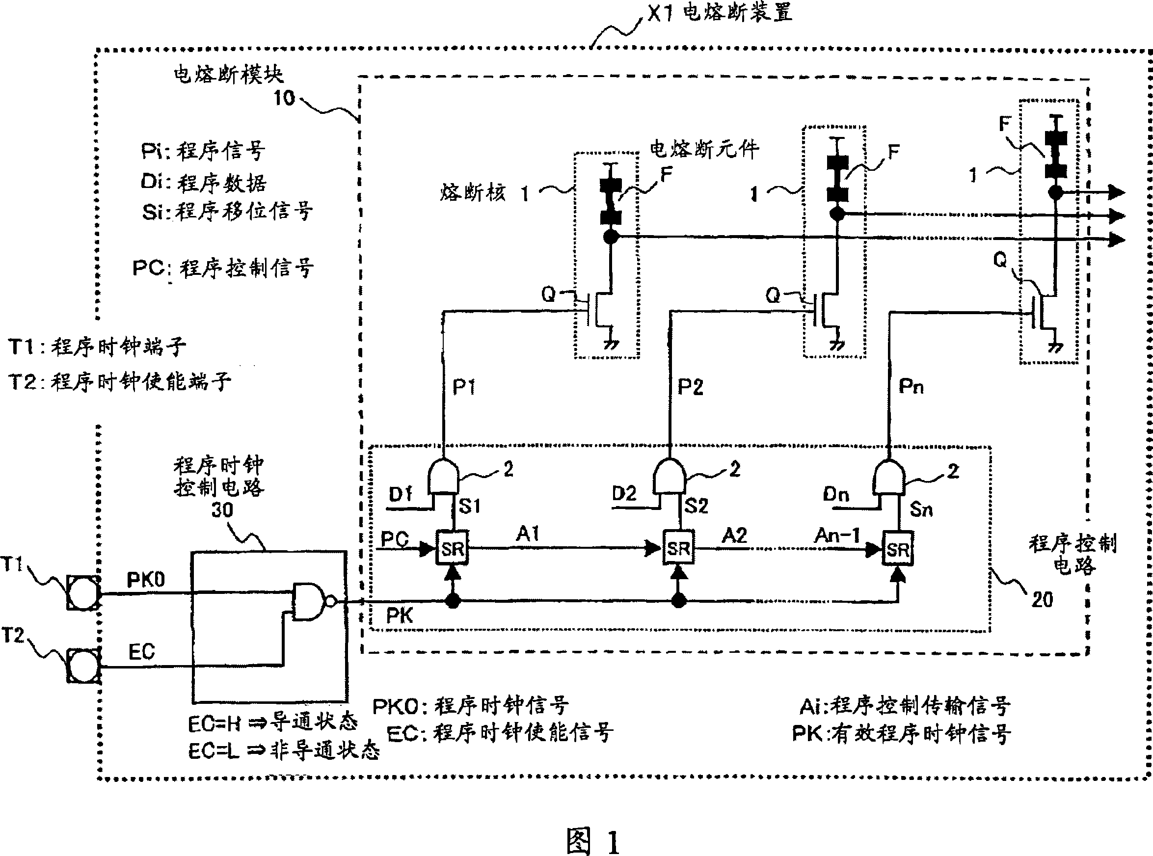
[0059] FIG. 1 is a circuit diagram showing the structure of an electrical fuse device according to a first embodiment. In FIG. 1 , reference numeral X1 denotes an electric fuse device, reference numeral 10 denotes an electric fuse module, reference numeral 20 denotes a program control circuit, and reference numeral 30 denotes a program clock control circuit. Reference numeral F denotes an electric fuse element made of silicide, polysilicon, or metal, one end of which is connected to an external power supply terminal. Reference numeral Q is a switching element, and the switching element Q includes an NMOS transistor, the drain of which is connected to the other end of the electric fuse element F, and the source of which is connected to the ground terminal. The electric fuse element F and the switching element Q constitute a fuse core 1 . "n" stages of fuse cores 1 are provided, where "n" is a natural number greater than or equal to 2.

[0060] The program control circuit 20 i...


PUM


Abstract

The invention provides an electrical fuse device comprising: a plurality of fuse cores, each having an electrical fuse element and a switching element serially connected to the electrical fuse element; a program control circuit generating a program shift signal by sequentially shifting a program control transmission signal in synchronization with an effective program clock signal and subsequently generating a program signal to be sent to each of the switching elements in the plurality of fuse cores based on program data and the program shift signal; and a program clock control circuit controlling the conducting and non-conducting states of a program clock signal in accordance with a program clock enable signal and, when the program clock signal is in a conducting state, transmitting the program clock signal to the program control circuit as the effective program clock signal.

Description

technical field [0001] The present invention relates to electric fuse devices, each electric fuse device includes a multi-stage fuse core, and each fuse core has an electric fuse element and a switch element connected in series, wherein, by synchronizing with a program clock signal, each The switching element provides program data, and the program can be executed for each electric fuse element. Background technique [0002] Electrical fuses are widely used in integrated circuits (LSI) including sequencers for high-frequency trimming. Electrical fuse devices include electrical fuse elements made of materials such as polysilicon. The electric fuse element is connected in series with the bipolar transistor, wherein processes such as "blowing" and "silicide" are performed by allowing a relatively large current of about 1 ampere to flow through the bipolar transistor. Such processing performed on the electric fuse element is hereinafter referred to as "electrical fuse element p...

Claims


Application Information

Patent Timeline
Patent Type & Authority Applications(China)
IPC IPC(8): G11C17/18
CPCG11C17/18G11C17/16
Inventor 西原竜二县泰宏川崎利昭角真一
Owner PANASONIC CORP
Learn More