
Signal reception system

A signal receiving and signal receiving technology, which is applied in the transmission system, TV system components, wireless communication, etc., can solve the problems of signal reception performance degradation, inability to receive signals, time delay, etc., and achieve reduced power consumption and stable signal reception Effect

Inactive Publication Date: 2008-02-13
SHARP KK
View PDF1 Cites 4 Cited by
  • Summary
  • Abstract
  • Description
  • Claims
  • Application Information

AI Technical Summary

Problems solved by technology

[0017] As mentioned above, it takes a certain amount of time for the monitoring circuit to correctly measure the sharply changing BER and the C / N of the received signal. During this period, the signal receiving performance of the system will naturally decrease. A time delay occurs until the control circuit 406 increases the power consumption of the entire system
[0018] In addition, since the above-mentioned structure controls the power consumption of the system sequentially according to predetermined increments (the method of controlling power consumption through the monitoring circuit and the control circuit will be described later), so when a strong interference signal is suddenly input , since the signal receiving system recovers gradually, it will take a certain amount of time to fully recover
[0019] Due to the above reasons, the system cannot maintain the signal reception performance matching the reception of the desired RF signal during the period from when a strong interference signal is input to when the control circuit 406 increases the power consumption of the entire system. Can't receive signal

Method used


Image

  • Signal reception system
  • Signal reception system
  • Signal reception system

Examples


Embodiment approach 1

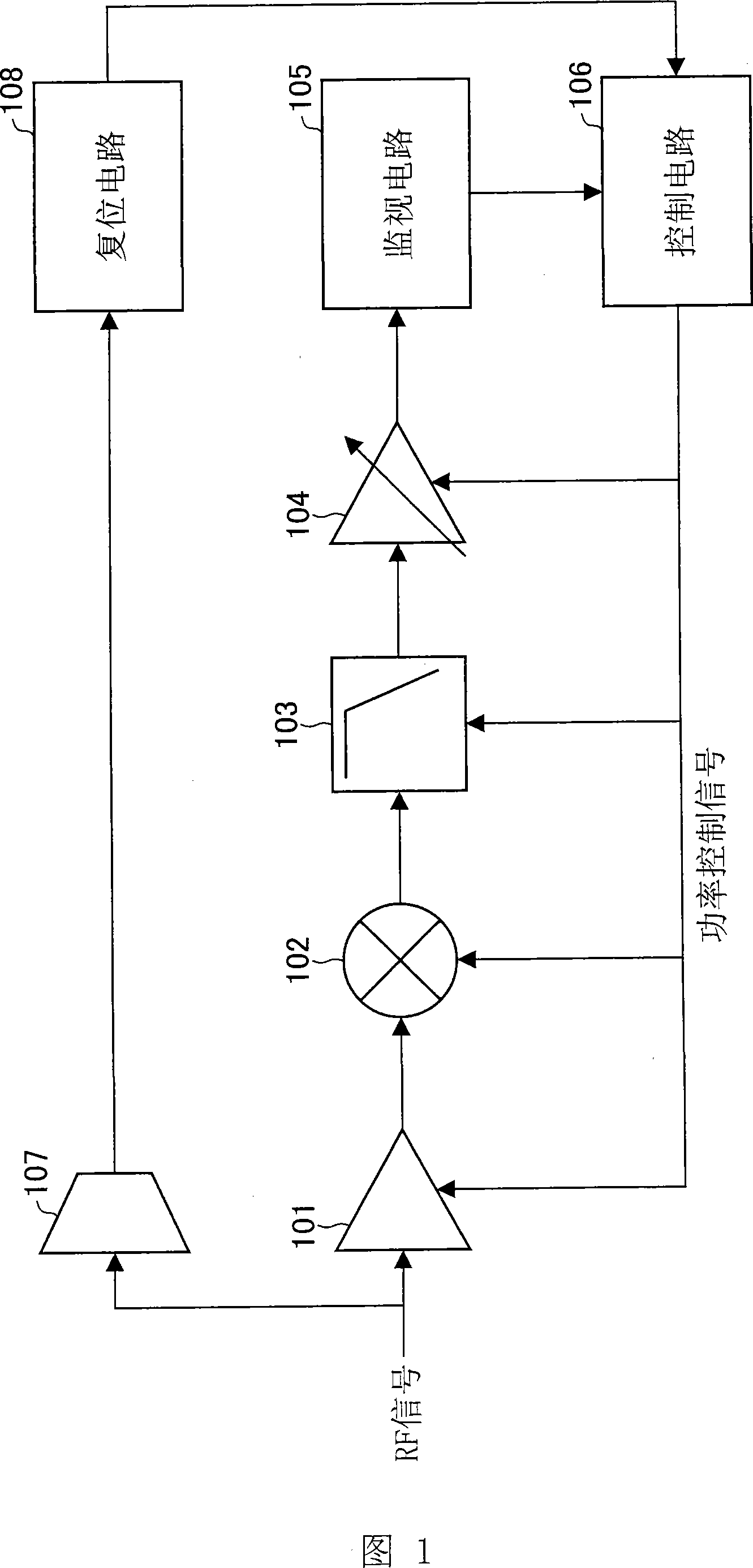
[0031] FIG. 1 shows the configuration of a signal receiving system according to an embodiment of the present invention.

[0032] The signal receiving system shown in FIG. 1 has: an amplifier 101, a mixer 102, a low-pass filter 103, and a variable gain amplifier 104 as a signal receiving processing section; a monitoring circuit 105 as a monitoring device; and a control circuit as a control device. 106. A detection circuit 107 as a detection device, and a reset circuit 108 as a reset device.

[0033] In addition, power consumption can be changed by the amplifier 101 , the mixer 102 , the low-pass filter 103 , and the variable gain amplifier 104 . In addition, amplifier 101, mixer 102, low-pass filter 103, variable gain amplifier 104, monitor circuit 105, and control circuit 106 can have the same configuration as the signal receiving system shown in FIG. 4 .

[0034] A detection circuit 107 , a reset circuit 108 , and a control circuit 106 are connected sequentially from an inpu...

Embodiment approach 2

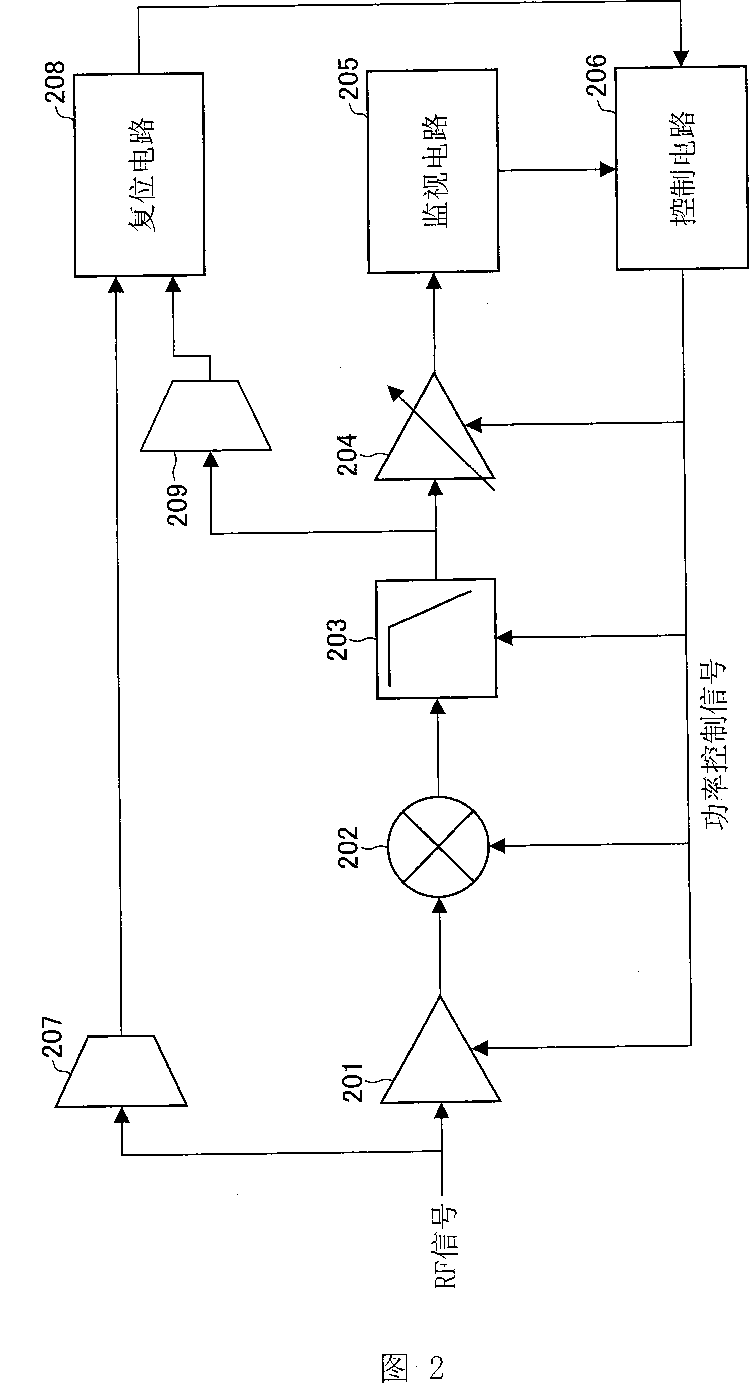
[0047] In Embodiment 1 above, when the input RF signal strength is greater than a predetermined set value, the detection circuit 107 outputs a high-level signal; when the reset circuit 108 receives a high-level signal from the detection circuit 107, the reset circuit 108 judges that there is Interfering with signal input and resetting the state of the system (returning the system to a state where the signal reception performance is high).

[0048] But in fact, the detection circuit 107 detects a high-level signal, in addition to the possibility that there is an input interference signal, it may also be the situation that the desired RF signal itself is relatively strong. Therefore, it is not preferable to uselessly increase the power consumption of the system by resetting the state of the system when the desired RF signal itself is strong. Therefore, in this embodiment and Embodiment 3 described later, the case of the interference signal input is further distinguished from the...

Embodiment approach 3

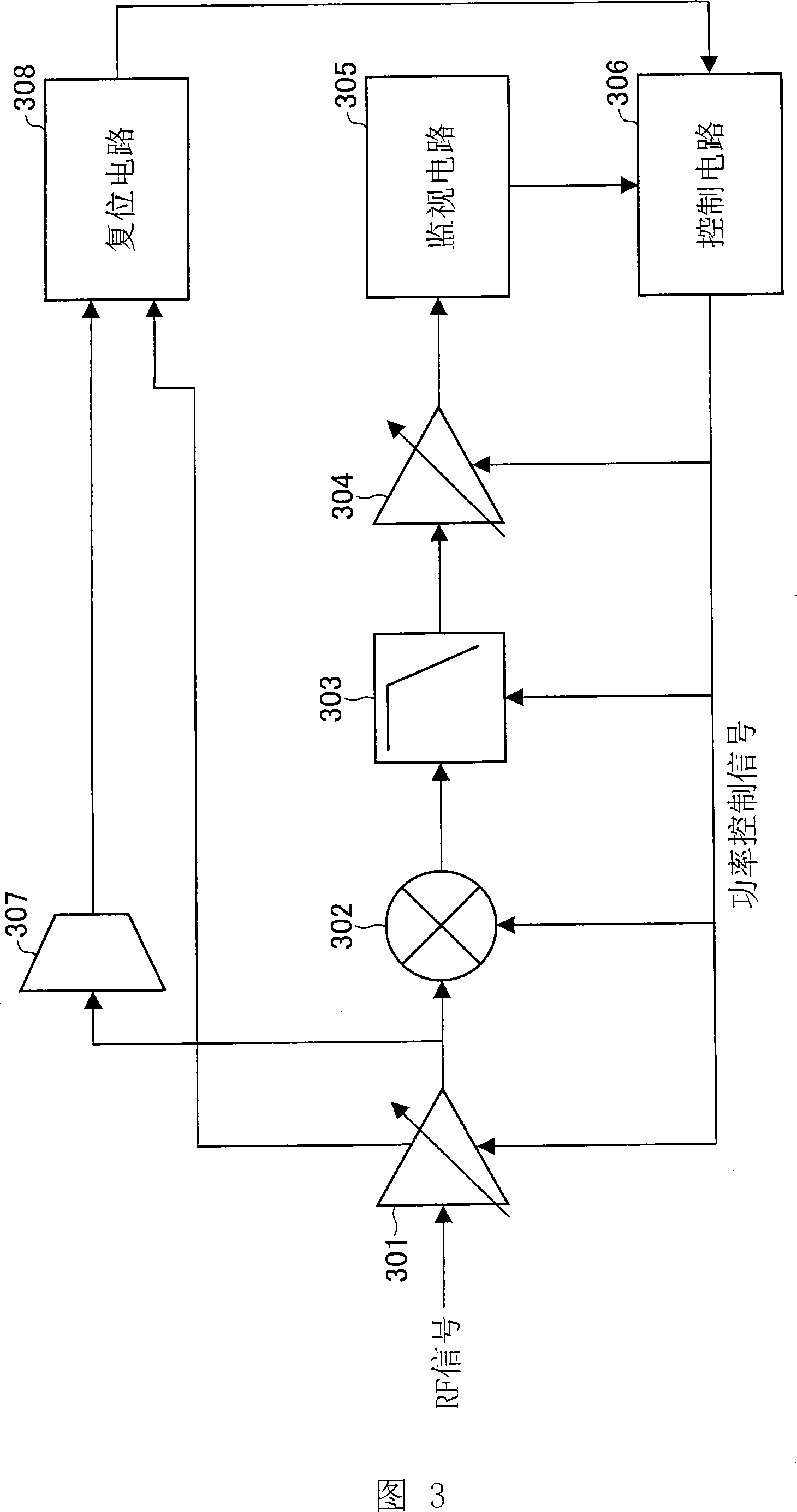
[0062] FIG. 3 shows a signal receiving system according to another embodiment of the present invention.

[0063] The signal receiving system shown in Fig. 3 has following structure, namely: variable gain amplifier 301, mixer 302, low-pass filter 303 and variable gain amplifier 304 as signal receiving processing section; Monitoring circuit 305 as monitoring device ; The control circuit 306 as the control device; The detection circuit 307 as the detection device; The reset circuit 308 as the reset device. In addition, the variable gain amplifier 301 adjusts the RF signal input from the input terminal to a level most suitable for the conversion frequency of the mixer 302 , and outputs it to the mixer 302 . In addition, the power consumption can be changed by the variable gain amplifier 301 , the mixer 302 , the low-pass filter 303 , and the variable gain amplifier 304 . In addition, the mixer 302, the low-pass filter 303, the variable gain amplifier 304, the monitor circuit 305,...


PUM


Abstract

The reception system of the present invention includes a detection circuit serving as detecting means for detecting that the strength of the receiver signal is equal to or greater than a predetermined value, and a resetting circuit serving as resetting means for, under instruction of the detection circuit, immediately increasing power consumption of the reception section when the detection circuit detects a large signal so as to bring back the state where the reception system ensures the greatest power consumption amount for the entire system and the sufficiently-desirable system performance. Consequently, this invention provides an effect of reducing power consumption amount of the entire system, and an effect of stable reception by preventing reception failure even when a large interfering signal is suddenly supplied due to a change in peripheral radio wave condition.

Description

technical field [0001] The present invention relates to a signal receiving system for a tuner device for receiving electric waves such as a television tuner, and more particularly to a signal receiving system for reducing power consumption during signal reception. Background technique [0002] As a prior art, for example, Patent Document 1 (Japanese Patent Application Laid-Open Publication No. 2002-252811, publication date: September 6, 2002) discloses a method for reducing power consumption in a TV tuner or the like. A signal receiving system used in tuner equipment for radio signal reception. [0003] Hereinafter, a configuration for reducing power consumption of a conventional signal receiving system will be described with reference to FIG. 4 . [0004] The prior art signal receiving system has: an amplifier 401, a mixer 402, a low-pass filter 403, and a variable gain amplifier 404 as a signal receiving processing section; a monitoring circuit 405 as a monitoring device;...

Claims


Application Information

Patent Timeline
IPC IPC(8): H04N5/44H04N5/00H04B1/16
CPCH04W52/0245Y02B60/50H04N5/52H04N5/4446H04N17/045H04N5/63H04N21/44209H04N21/4436H04N21/6131Y02D30/70
Inventor 久保田晋平
Owner SHARP KK
Learn More