Backlight module and light guiding board employed by same

A technology of backlight module and light guide plate, which is applied in the field of light guide plate, can solve the problems such as the inclination angle optimization design of the groove surface and the inability to further improve the light utilization rate, etc.

Inactive Publication Date: 2008-02-20
WINTEK CORP
View PDF0 Cites 20 Cited by
  • Summary
  • Abstract
  • Description
  • Claims
  • Application Information

AI Technical Summary

Problems solved by technology

However, in the above-mentioned known designs, no matter whether the groove structure used as the light guide dots is produced by tool processing or anisotropic e

Method used


Image

  • Backlight module and light guiding board employed by same
  • Backlight module and light guiding board employed by same
  • Backlight module and light guiding board employed by same

Examples


Example Embodiment

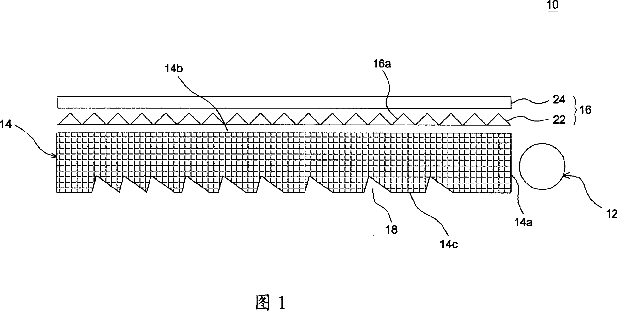
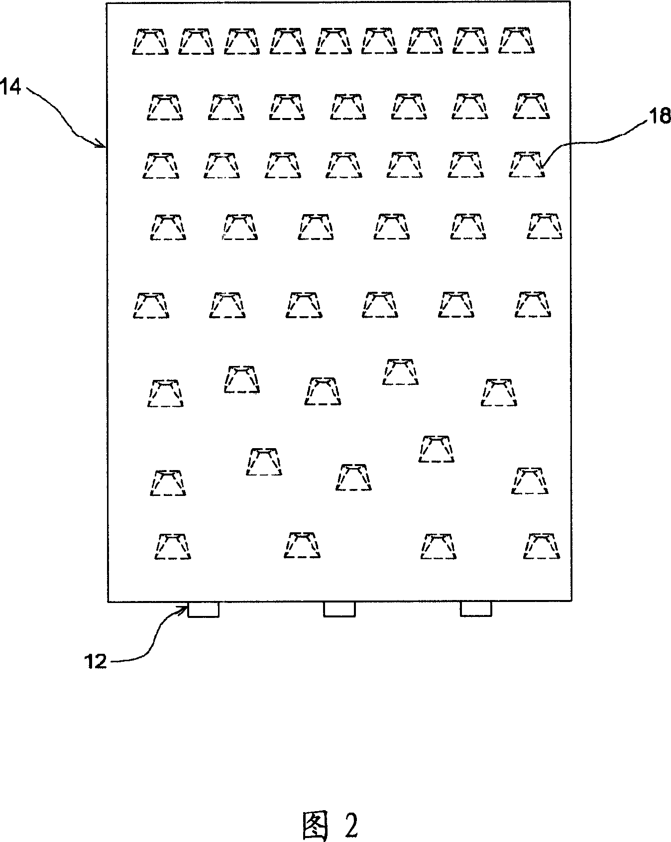
[0017] FIG. 1 is a schematic diagram showing a backlight module 10 according to an embodiment of the present invention. As shown in FIG. 1 , the backlight module 10 includes a light source 12 , a light guide plate 14 and a set of brightness enhancement films (BEF) 16 . The light guide plate 14 has a light input end 14a, a light output surface 14b, and a light reflection surface 14c located on the opposite side of the light output surface 14b, and a plurality of concaves concave toward the light output surface 14b side are formed on the light reflection surface 14c. Groove structure 18. The light source 12 is adjacent to the light input end 14a. The light emitted by the light source 12 is reflected or refracted by the groove structure 18 on the light reflective surface 14c, and then transmitted to a display panel (not shown) through the light output surface 14b. In this embodiment, the enhancement sheet 16 is composed of a double prism sheet including the first prism sheet 22 ...


PUM


Abstract

The utility model provides a backlight module, comprising a light source, a light guide plate and a prism brightness enhancement film. A plurality of groove structures are arranged on the light reflecting surface of the light guide plate, each groove structure has a first concaved surface facing to the light source and a second concaved surface backward the light source, the included angle of the first concaved surface and the flat light reflecting surface is not exceed 35 degree. The utility model has the advantages of increasing the luminous flux of angular field of view to human eye, reducing the luminous flux totally reflected by microprism structure of the prism brightness enhancement film, enhancing effectively the brilliance of light guide plate and promoting further the light extraction efficiency of backlight module.

Description

technical field [0001] The invention relates to a backlight module with good light extraction efficiency and a light guide plate used in the backlight module. Background technique [0002] Traditionally, to manufacture a light guide plate of a backlight module, it is common to use a material such as a steel plate to etch the mold core to form dots. However, on the one hand, the crystalline structure of the steel plate is amorphous, and structural defects are often encountered during the etching process, and the structural defects of each steel plate are different, which makes the etching reproducibility of the steel plate poor; on the other hand, because an isotropic etching solution is usually used for In this etching process, it is difficult to prevent the etching holes from being enlarged, and it is impossible to control the inclination angle of each dot after forming, so that the luminance of the manufactured light guide plate is not good. [0003] Therefore, in the kno...

Claims


Application Information

Patent Timeline
IPC IPC(8): G02F1/1335G02B6/00
Inventor 陈冰彦黄国瑞张佩银
Owner WINTEK CORP
Why Eureka
Try Eureka