
Automatic control device for differential distribution network

A technology of distribution network automation and control devices, applied in circuit devices, emergency protection circuit devices, electrical components, etc., can solve the problems of repeated power outages and power transmissions, reducing the service life of switching appliances, and short-circuit impact of power grids, etc. The number of actions and the number of power outages and power transmissions, the rapid restoration of power supply, and the effect of ensuring continuity

Active Publication Date: 2008-02-20
COOPER NINGBO ELECTRIC
View PDF0 Cites 5 Cited by
  • Summary
  • Abstract
  • Description
  • Claims
  • Application Information

AI Technical Summary

Problems solved by technology

In order to overcome the existing distribution network automation device when looking for the fault location of the distribution network line, the switching appliances have frequent actions, the number of repeated power failures, the restoration of power supply time is too long, the reliability is not high, and the service life of the switching appliances is reduced. Insufficient to bring unnecessary short-circuit impact, the present invention provides a differential principle that adopts the differential principle to locate the section, can quickly lock the faulty section, reduce the number of actions of switching appliances, quickly restore power supply, and avoid short-circuit impact on the power grid. Dynamic distribution network automation control device

Method used

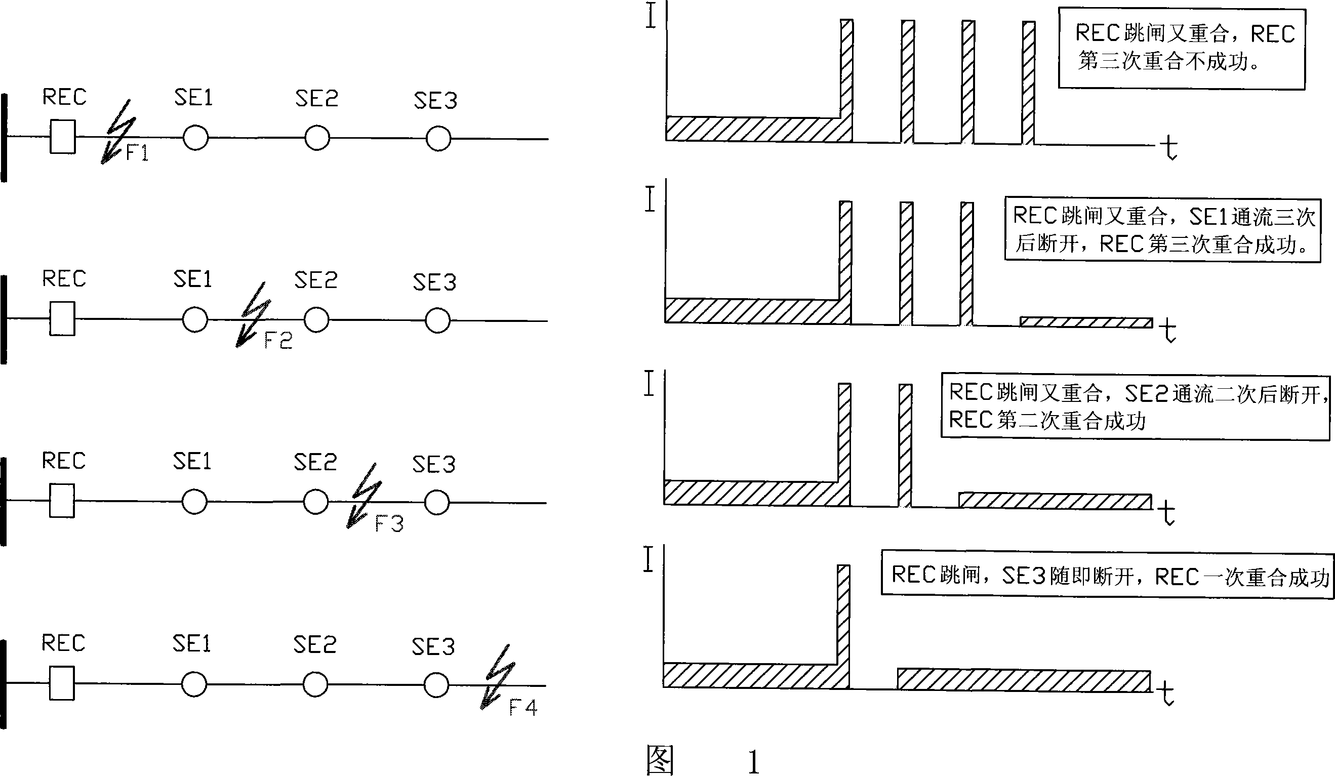
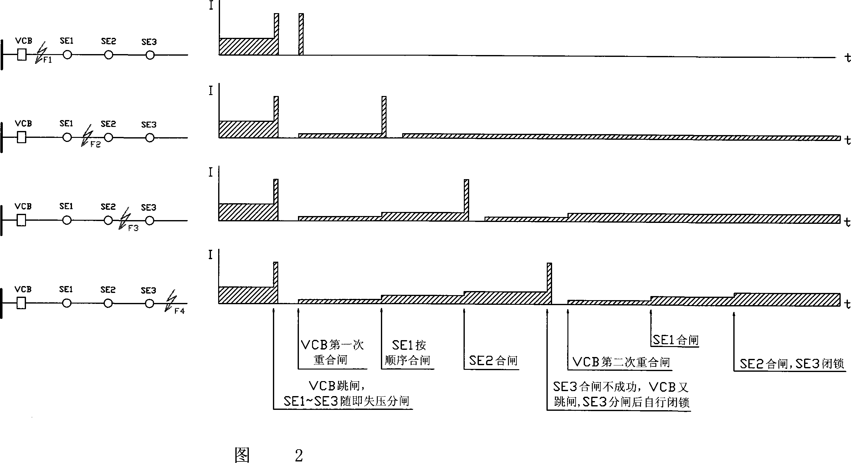
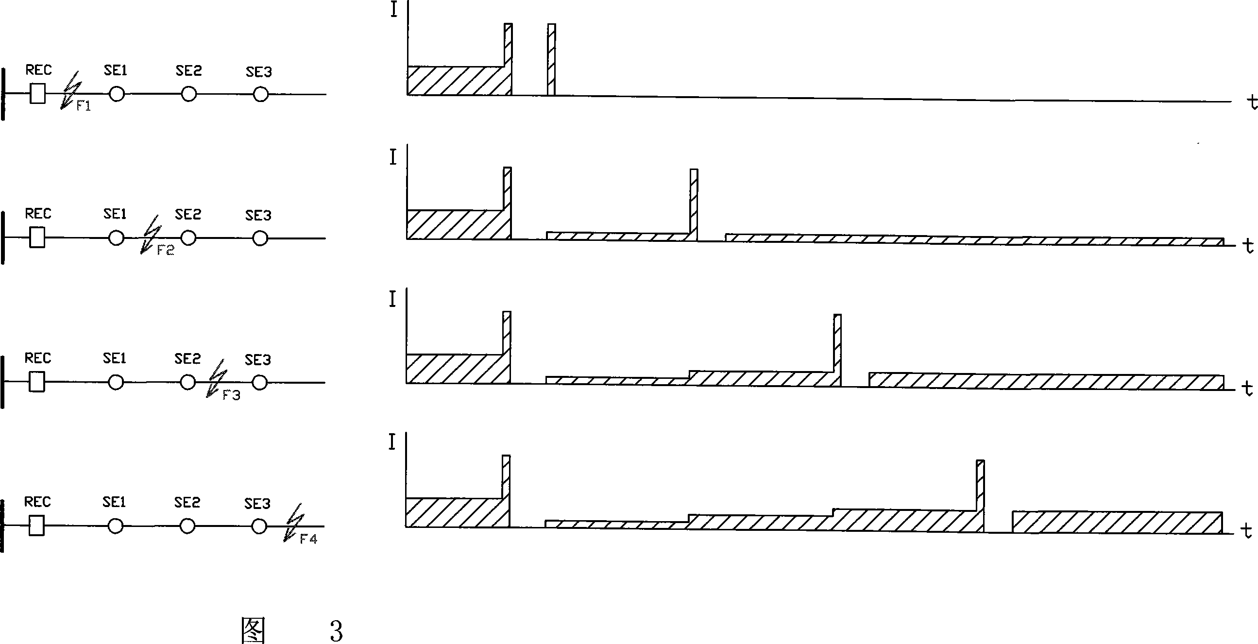

Image

  • Automatic control device for differential distribution network
  • Automatic control device for differential distribution network
  • Automatic control device for differential distribution network

Examples


Embodiment Construction

[0034] The present invention will be further described below in conjunction with the accompanying drawings.

[0035] Referring to Fig. 4 and Fig. 5, a differential distribution network automation control device controls the main power supply switch and the section switch installed in the line section, and the control device also includes: used to set the fault current initial Threshold, to collect the signals of A and C phase current transformers, and shift the phases of A and C phase current signals to make the leading edges basically overlap, and to trigger and locate fault current collectors; used to identify faults in power distribution automation power supply systems Address coding and decoder corresponding to the trigger signal of each segment switch on the line and the specific address code; used to modulate each segment switch and the trigger signal with address code of the two segment switches before and after, and A carrier frequency device for carrier frequency comm...


PUM


Abstract

The utility model relates to an automatic control device of differential distribution network, comprising three current transformers of phase A, B, and C arranged in the lines of the distribution power network, and two sectional switches arranged on both sides of the section of the lines. The utility model also comprises a fault current collector, an address encoder, an address decoder, a carrier frequency device, a differential comparison and identification unit, and a motor carrier power supply unit. The current transformers of phase A and C are connected with the collector of faulting current, and the current transformer of phase B is connected with the motor carrier power supply unit which is connected with a trip coil of the sectional switch. Besides, the carrier frequency device is connected with the address encoder and the address decoder, and the fault current collector is connected with the differential comparison and identification unit which is connected with the trip coil of the sectional switch. The utility model has the advantages that: due to adopting the differential device to position the working section in a long distance, the faulting section can be identified quickly, the action number of the switch can be reduced, the power can be resupplied soon, and the impact caused by short circuit to the power network can be avoided.

Description

(1) Technical field [0001] The invention belongs to distribution network automation equipment, in particular to a distribution network automation control device. (2) Background technology [0002] The failure probability of overhead lines is relatively high. The modern distribution network system uses segment switches (load switches) to divide long lines into multiple line segments for operation. In the blackout area, improve the reliability of the power supply of the distribution network system. [0003] In order to improve the reliability of the power supply of the 10kV overhead distribution network system, my country has adopted distribution network automation equipment technology since the late 1980s, and introduced and developed various types of high-voltage electrical equipment and control devices such as reclosers and sectionalizers. . The purpose of automatic control technology of feeder lines in distribution network system is to quickly identify line faults and iso...

Claims


Application Information

Patent Timeline
IPC IPC(8): H02J13/00H02H7/22G01R31/08
CPCY04S10/20Y02E60/725Y02E60/00
Inventor 薛培鑫沈忠威
Owner COOPER NINGBO ELECTRIC
Learn More