
A cooling system for permanent magnetic generator

A permanent magnet generator and cooling system technology, which is applied in the direction of machines/engines, cooling/ventilation devices, electrical components, etc., can solve the problems of reducing the service life of motors, reducing the power of permanent magnet motors, and thermal demagnetization of permanent magnets, etc., to achieve extended The effect of service life, reducing heat conduction, and smooth air flow

Inactive Publication Date: 2008-02-20
WUXI KIPOR POWER CO LTD
View PDF0 Cites 8 Cited by
  • Summary
  • Abstract
  • Description
  • Claims
  • Application Information

AI Technical Summary

Problems solved by technology

[0003] Among the rare earth permanent magnet materials currently used in generators, sintered NdFeB is widely used in high-power permanent magnet generators due to its large magnetic energy product and intrinsic coercive force, but sintered NdFeB permanent The remanence induction temperature coefficient of the magnet (-0.08% / ℃~-0.13% / ℃) and the intrinsic coercive force temperature coefficient (-0.5% / ℃~-0.65% / ℃) are relatively large compared with other permanent magnets, so The temperature stability is relatively poor, and the stable working temperature of sintered NdFeB is generally around 140°C
When the temperature of the motor is close to or exceeds this temperature, the permanent magnets in the motor are prone to thermal demagnetization, and a large part of this demagnetization is irreversible, which causes the power drop and performance reduction of common permanent magnet motors; another On the one hand, the temperature of the stator coil is too high, which will easily cause serious aging of the insulation and greatly reduce the service life of the motor

Method used


Image

  • A cooling system for permanent magnetic generator
  • A cooling system for permanent magnetic generator
  • A cooling system for permanent magnetic generator

Examples


Embodiment Construction

[0015] Below the present invention will be further described in conjunction with the embodiment in the accompanying drawing:

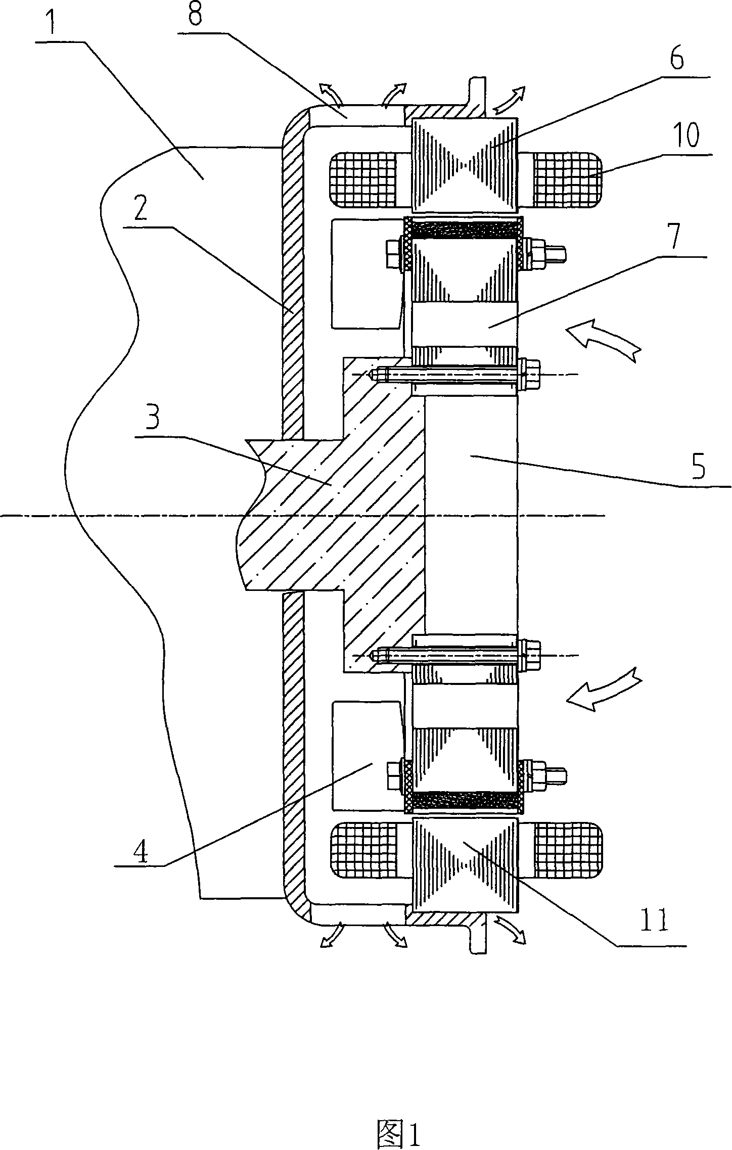
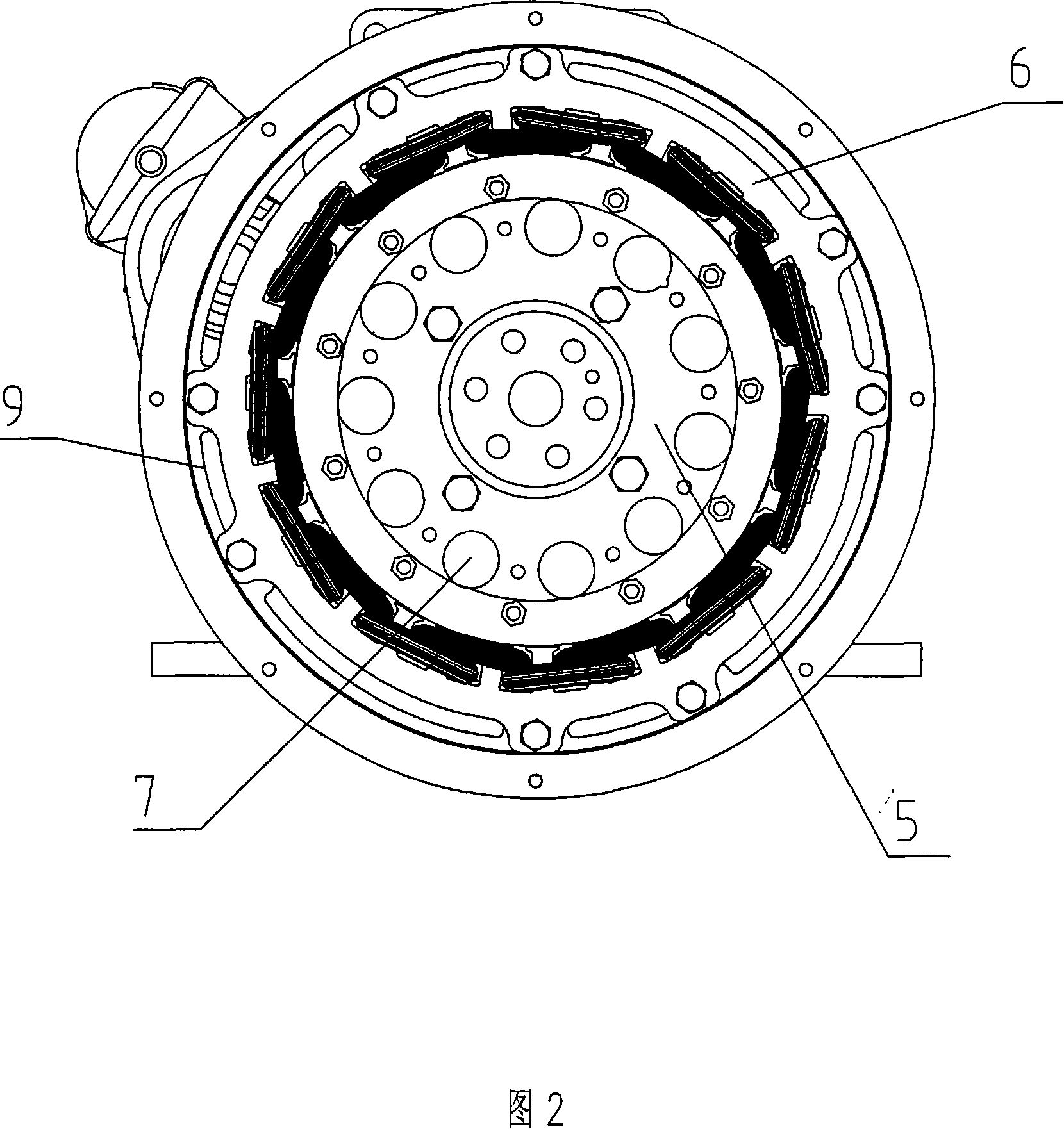
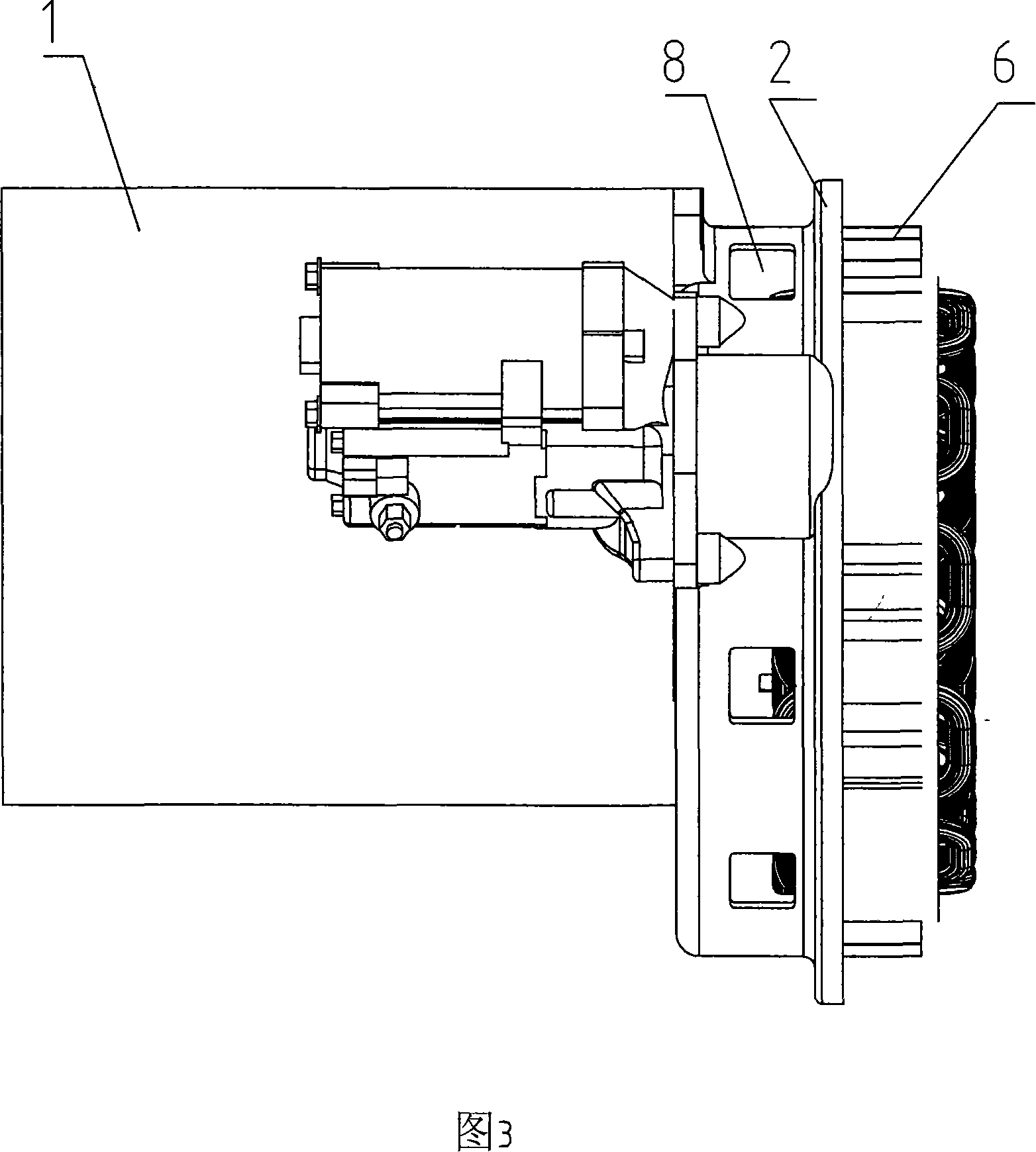
[0016] The present invention mainly consists of engine 1, engine flywheel housing 2, engine crankshaft 3, fan blade 4, permanent magnet generator rotor 5, permanent magnet generator stator 6, air inlet hole 7, exhaust hole 8, exhaust hole 9, stator Composed of coil 10 and permanent magnet generator 11 etc.

[0017] The present invention is mainly made up of engine 1, engine flywheel casing 2 and permanent magnet generator 11, and permanent magnet generator stator 6 is installed on the engine flywheel casing 2, leaves gap between engine flywheel casing 2 and permanent magnet generator stator 6, so The outer diameter of the above-mentioned engine flywheel housing 2 is provided with at least two or more exhaust holes 8 . Said engine flywheel housing 2 and the groove provided on the outer diameter of the permanent magnet generator stator 6 form at least t...


PUM


Abstract

The utility model relates to a cooling system of permanent magnet generators, in particular to a cooling system of high power permanent magnet generators, which comprises an engine and a permanent magnet generator; wherein, the stator of the permanent magnet generator is arranged on the flywheel casing of the engine; the rotor of the permanent magnet generator is arranged on the crank shaft of the engine. The utility model is characterized in that: the end with fan blades of the rotor is connected with the crank shaft of the engine; the fan blades connected with the rotor are arranged between the flywheel casing of the engine and the permanent magnet generator. The rotor and the stator of the permanent magnet generator are forcibly cooled by the cooling wind generated by the fan blades, which are driven by the rotation of the rotor, The heat transferred towards the permanent magnet of the rotor from the stator is reduced and the effect is good. The cooling efficiency of the stator coil of the permanent magnet generator and the permanent magnet rotor can be greatly improved without increasing the overall size of the generator set, thus ensuring the reliability of the continuous operation, and prolonging the service life of the permanent magnet generator.

Description

technical field [0001] The invention relates to a cooling system of a permanent magnet generator, in particular to a cooling system of a high-power permanent magnet generator. Background technique [0002] In the prior art, when the general diesel digital permanent magnet generator is working, the temperature inside the body is relatively high, especially the high-power diesel digital generator set, which is equipped with a permanent magnet generator. Due to the miniaturization of the shape, generally there is no cooling fan, and the generator is cooled by the free circulation of air in the case. The generator set with this structure cannot run continuously for a long time. Since there is no direct cooling of the generator, the heat generated by the stator coil cannot be discharged quickly, so that the temperature rise of the rotor equipped with permanent magnets also rises quickly. For permanent magnet generators, temperature is a direct factor that determines the performa...

Claims


Application Information

Patent Timeline
IPC IPC(8): H02K9/04
CPCH02K9/06F02B63/04H02K7/1815F02B63/042
Inventor 肖亨琳
Owner WUXI KIPOR POWER CO LTD
Learn More