Clock signal output apparatus and control method of same, and electric apparatus and control method of same

A clock signal output and clock signal technology, which is applied in the field of clock signal output devices, can solve problems such as poor frequency accuracy and temperature changes in oscillation frequency, and achieve the effects of reducing driving times, improving precision, and avoiding increased power consumption

Inactive Publication Date: 2008-02-20
SEIKO EPSON CORP
View PDF3 Cites 17 Cited by
  • Summary
  • Abstract
  • Description
  • Claims
  • Application Information

AI Technical Summary

Problems solved by technology

[0006] However, the conventional temperature-compensated crystal oscillator adopts a structure that temperature-compensates the temperature characteristic of the crystal having the third-order characteristic according to the temperature characteristic of the capacitance having the second-ord

Method used


Image

  • Clock signal output apparatus and control method of same, and electric apparatus and control method of same
  • Clock signal output apparatus and control method of same, and electric apparatus and control method of same
  • Clock signal output apparatus and control method of same, and electric apparatus and control method of same

Examples


no. 1 Embodiment approach

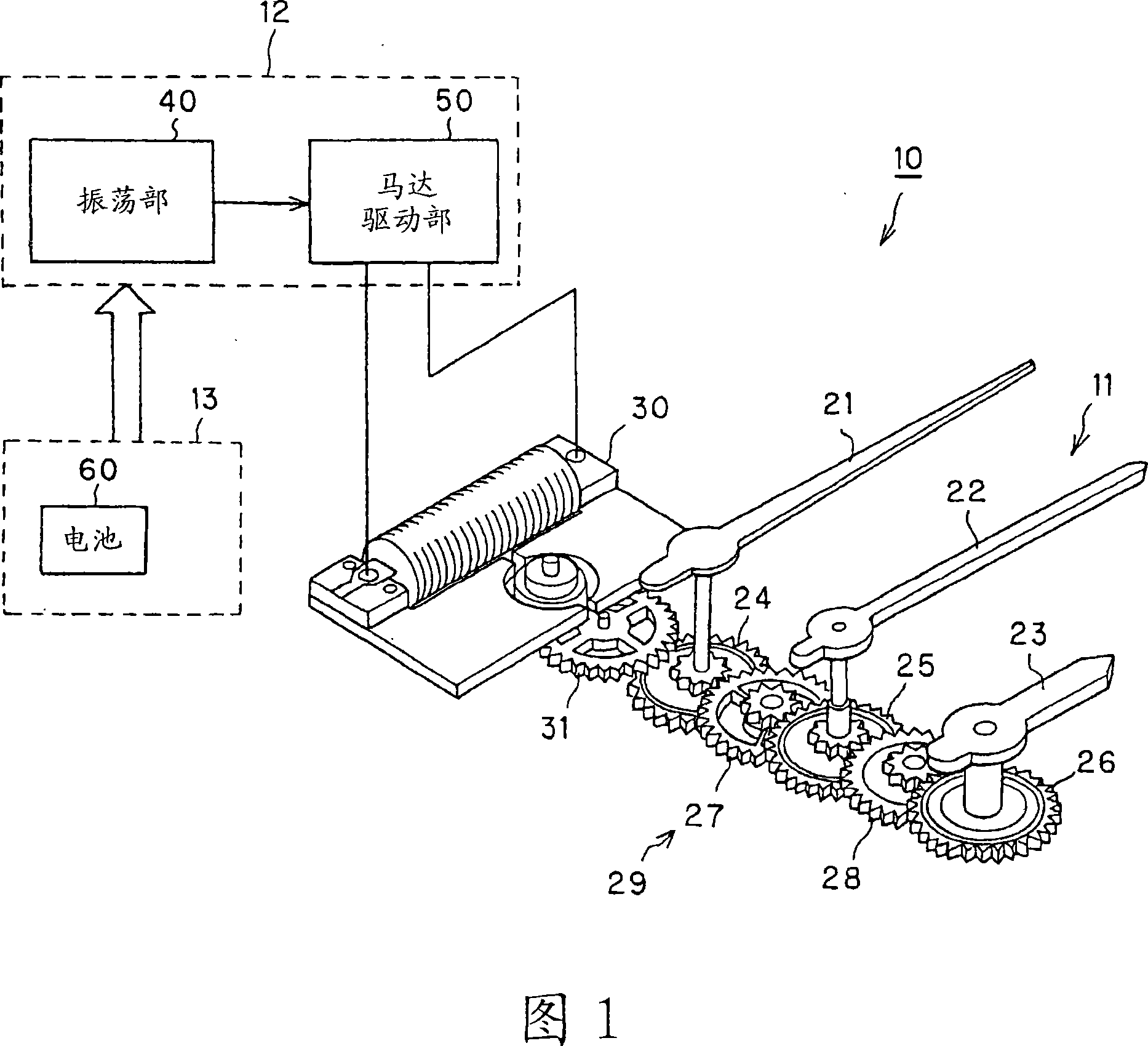
[0052] FIG. 1 is a block diagram showing the structure of a wristwatch according to one embodiment of the present invention. This wrist watch (electronic timepiece) 10 is configured to include: a hand movement mechanism 11 and a drive unit 12 constituting a timepiece module; and a power supply unit 13 for supplying operating power to the timepiece module.

[0053] The hand movement mechanism 11 constitutes a time display unit that drives the second hand 21, the minute hand 22, and the hour hand 23 to display the time. The wheels 26 are connected to each other via intermediate wheels 27 , 28 . One end of the second hand 21 is attached to the rotation axis of the second wheel 24 , one end of the minute hand 22 is attached to the rotation axis of the second wheel 25 , and one end of the hour hand 23 is attached to the rotation axis of the hour wheel 26 . The drive gear 31 of the drive motor 30 meshes with the second wheel 24, and the second wheel 24 is rotationally driven by the...

no. 2 Embodiment approach

[0074] The wristwatch 10A of the second embodiment has, as shown in FIG. The first information (reference oscillator influence information) that affects the operation of the oscillator) 41, etc.; and the second detection unit (high-precision oscillator influence information detection unit) 80, which detects the 42, etc., the second information (high-precision oscillator influence information) that affects the operation. Hereinafter, the same reference numerals are assigned to the substantially same configurations as those of the first embodiment, detailed descriptions are omitted, and different parts will be described in detail.

[0075] The first detection unit 70 includes: a temperature detection unit 71 that detects temperature (including outside air temperature); a voltage detection unit 72 that detects a power supply voltage; and a posture detection unit 73 that detects the posture of the wristwatch 10A. Here, the temperature change is the main cause of the frequency cha...

no. 3 Embodiment approach

[0088] A wristwatch 10B of the third embodiment includes a temperature detection unit 71 that detects temperature (reference oscillator influence information), and the temperature detection unit 71 is connected to the intermittent time management unit 47 of the oscillation unit 40 as shown in FIG. 11 . The intermittent time management unit 47 has a counter 47a1 for counting the update period P1 of the calibration data and a counter 47b2 for counting the temperature detection interval P2, and is configured to be able to count the update period P1 and the temperature detection interval P2.

[0089] Furthermore, in the memory 46a, as shown in FIG. 12, correction data D1(k) (k=temperature) corresponding to each temperature is memorize|stored. In addition, the figure shows the case where the correction data D1(k) is set every 1 degree. However, from the viewpoint of reducing the amount of data, rough setting can be performed, for example, every 5 degrees. The correction data D1(n) ...


PUM


Abstract

Provided are a clock signal outputting device and its control method, and an electronic device and its control method, which can enhance the precision of a clock signal while avoiding an increase in the entire power consumption even if a highly precise oscillator of a relatively high power consumption is used. The clock signal output device includes a quartz oscillator (41) for generating a reference clock signal (CL1), and generates and outputs an outputted clock signal (CL0) of a predetermined frequency from the reference clock signal (CL1). The clock signal output device further includes an atomic oscillator (42) for generating a clock signal (CL2) of a higher precision than that of the quartz oscillator (41), an intermittent time managing unit (47) for driving the atomic oscillator (42) intermittently, and a correction unit (46) for acquiring correction data to correct the displacement of the outputted clock signal (CL0) with reference to the clock signal (CL2), each time the atomic oscillator (42) is driven, thereby to correct the outputted clock signal (CL0) on the basis of that correction data.

Description

technical field [0001] The present invention relates to a clock signal output device having a reference oscillator for generating a reference clock signal and generating and outputting an output clock signal of a predetermined frequency based on the reference clock signal, a control method thereof, an electronic device and a control method thereof. Background technique [0002] Conventionally, there is an electronic timepiece that divides the frequency of a reference clock signal output from a reference oscillator to generate, for example, a 1 Hz signal, and keeps time based on the 1 Hz signal. Such an electronic timepiece is known as an annual difference clock, which uses a temperature compensated crystal oscillator (Temperature Compensated Crystal Oscillator) as a reference oscillator, and realizes an annual difference within ±tens of seconds (for example, Patent Document 1). In recent years, standard oscillators using atomic oscillators have been proposed (for example, Pa...

Claims


Application Information

Patent Timeline
IPC IPC(8): G04G3/00G04G3/04
CPCG04C13/00G04F5/14G04G3/00
Inventor 关重彰井上胜豊
Owner SEIKO EPSON CORP
Why Eureka
Try Eureka