Electromagnetic variation paddle mechanism of windmill generator

An electro-mechanical and electromagnetic technology, applied in the field of electromagnetic pitch mechanism of wind turbines, can solve problems such as troublesome maintenance, and achieve the effects of easy maintenance, no contact friction and vibration, and fast response speed.

Inactive Publication Date: 2008-03-12
包头市汇全稀土实业(集团)有限公司
View PDF0 Cites 6 Cited by
  • Summary
  • Abstract
  • Description
  • Claims
  • Application Information

AI Technical Summary

Problems solved by technology

And the brakes used are generally contact brake

Method used


Image

  • Electromagnetic variation paddle mechanism of windmill generator
  • Electromagnetic variation paddle mechanism of windmill generator

Examples


Embodiment 1

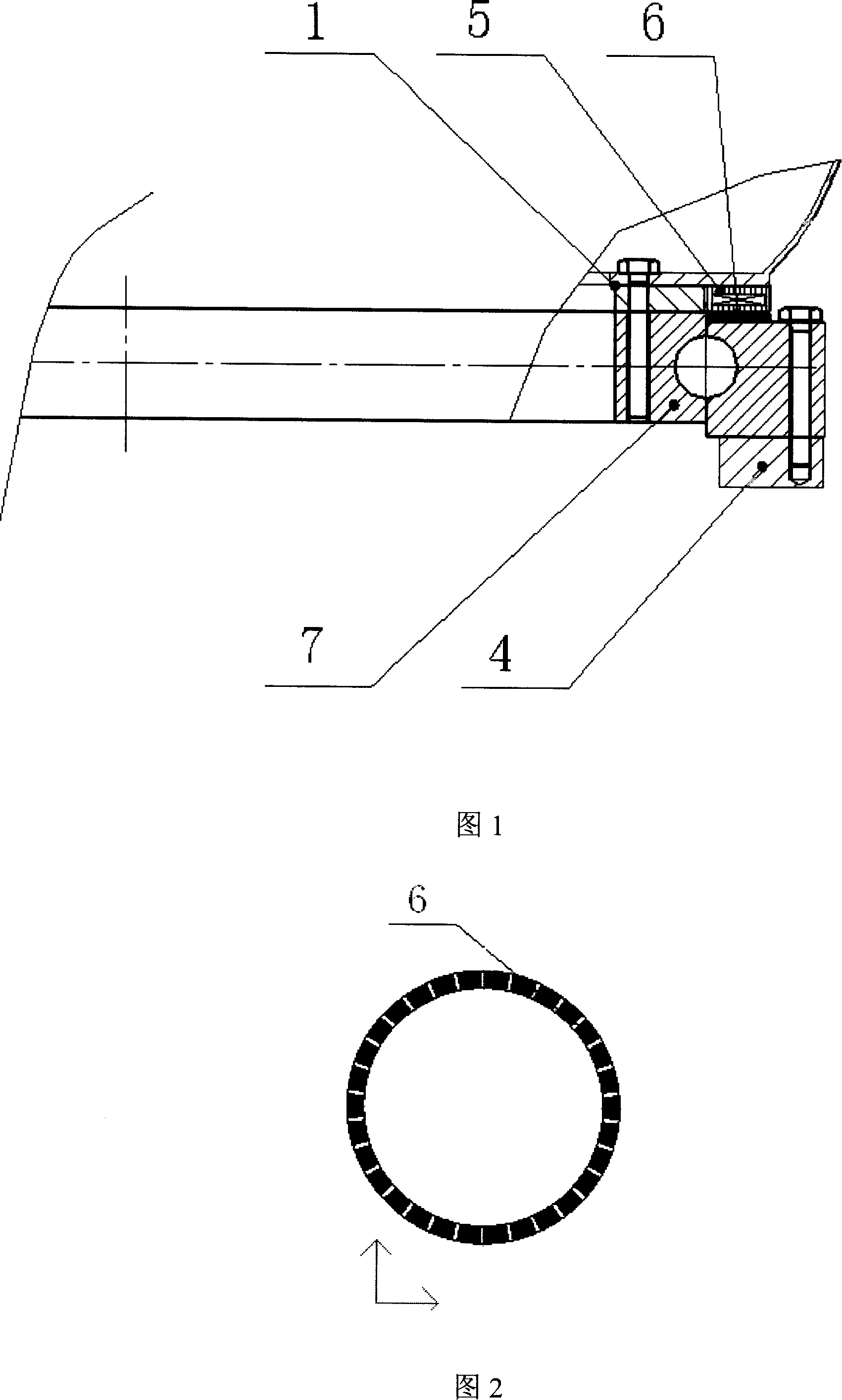
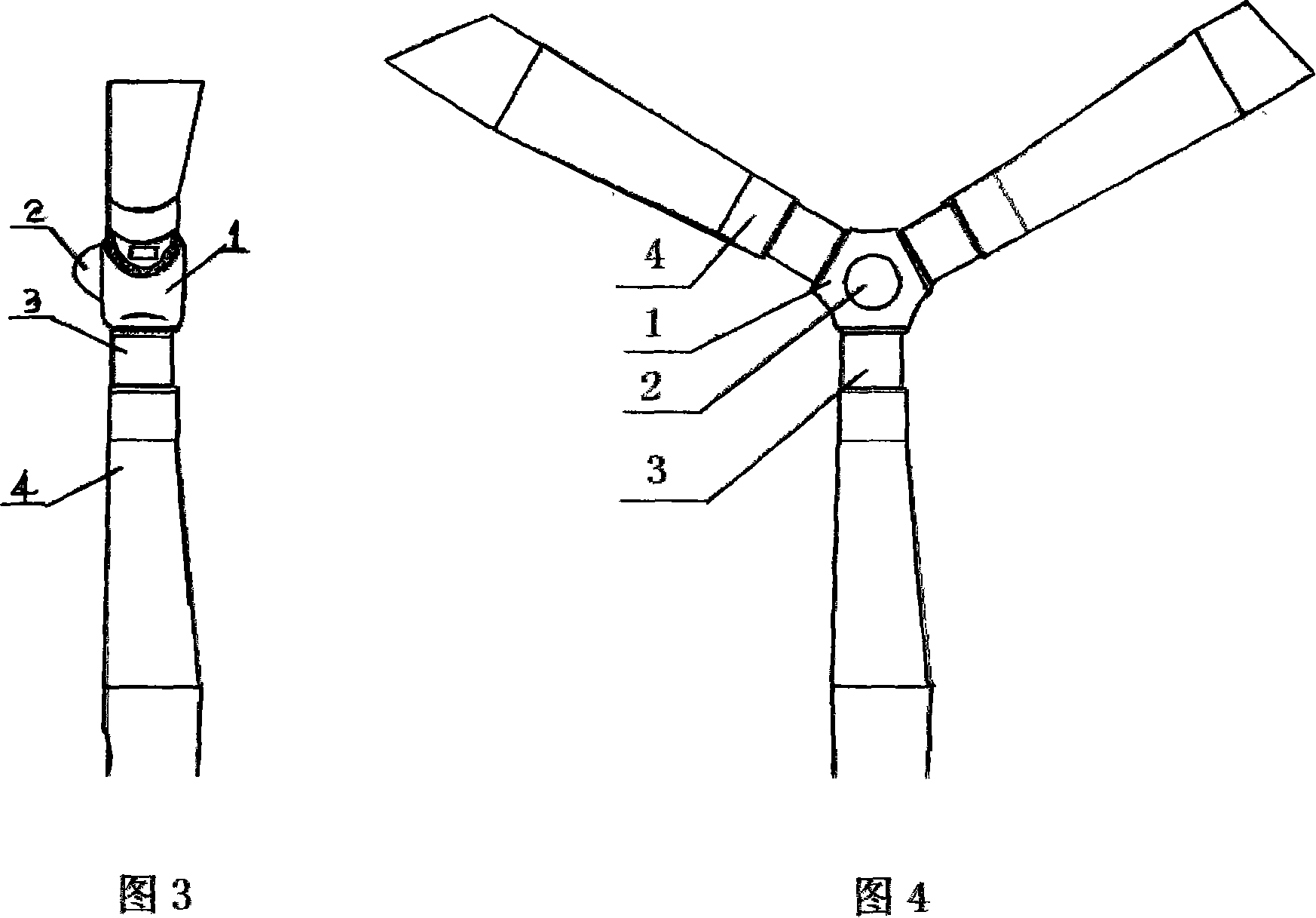
[0011] The present invention is made up of hub 1, fairing 2, variable pitch extension joint 3, blade 4, motor winding stator 5, magnetic steel rotor 6, motor winding stator 5 and magnetic steel rotor 6 form permanent magnet stepping motor, winding The stator 5 is connected to the inner ring of the slewing support bearing 7, and the magnetic steel rotor 6 is connected to the outer ring of the slewing support bearing 7 to form a permanent magnet stepping motor support and rotation mechanism. The inner ring of the slewing support bearing 7 is connected to the blade 4 through bolts. Connected, the outer ring of the slewing support bearing 7 is connected with the hub 1 by bolts to form a pitch-changing mechanism.

[0012] Working principle: After the winding stator 2 of the motor passes a group of pulse electricity, it drives the permanent magnet stepping rotor to rotate 1 pole, and drives the blades to rotate at a certain angle to achieve the purpose of pitch change. If it is a co...

Embodiment 2

[0014] The present invention is made up of hub 1, fairing 2, variable pitch extension joint 3, blade 4, motor winding stator 5, magnetic steel rotor 6, motor winding stator 5 and magnetic steel rotor 6 form permanent magnet stepping motor, motor winding The wire stator 5 and the magnetic steel rotor 6 form a permanent magnet stepping motor, the winding stator 5 is connected with the outer ring of the slewing support bearing 7, and the magnetic steel rotor 6 is connected with the inner ring of the slewing support bearing 7 to form a permanent magnet stepping motor support and In the rotating mechanism, the outer ring of the slewing support bearing 7 is connected to the blade 4 through bolts, and the inner ring of the slewing support bearing 7 is connected to the hub 1 through bolts to form a pitch-changing mechanism.

Embodiment 3

[0016] The present invention is made up of hub 1, fairing 2, variable pitch extension joint 3, blade 4, motor winding stator 5, magnetic steel rotor 6, motor winding stator 5 and magnetic steel rotor 6 form permanent magnet stepping motor, winding The stator 5 is connected to the inner ring of the slewing support bearing 7, and the magnetic steel rotor 6 is connected to the outer ring of the slewing support bearing 7 to form a permanent magnet stepping motor support and rotation mechanism. The outer ring of the slewing support bearing 7 is connected to the blade 4 through bolts. Connected, the inner ring of the slewing support bearing 7 is connected with the hub 1 through bolts to form a pitch-changing mechanism.


PUM


Abstract

The invention relates to an electromagnetic propeller-switching mechanism for wind power generators and belongs to the field of wind power generation. The invention is characterized in that a motor wound stator and a magnet steel rotor is made up into a permanent magnet step motor; the stator and rotor in the permanent magnet step motor are respectively connected with an internal rotary support and an external rotary support, so as to form a support and rotation system for the permanent magnet step motor. The internal and external rotary supports are respectively connected with vanes and hubs through bolts to form a propeller-switching mechanism. The invented propeller-switching system is not arranged with gear meshing, for which it is not possible to result in gear wearing and damage; meanwhile, the propeller-switching system has advantages of neither gearbox oil leakage nor damping, and easy maintenance. Braking and quick response are maitained through permanent magnet magnet steel and DC current without contact friction or vibration; meanwhile, the invention can effectively resolve tower shadow phenomenon.

Description

1. Technical field [0001] The invention relates to an electromagnetic pitch-changing mechanism of a wind power generator, which belongs to the field of wind power generation. 2. Background technology [0002] The pitch wind turbine drives the hub to rotate through the blades, and the angle of attack of the blades must be changed in order to adjust the rotation speed and output power of the hub. Generally, the rotation speed and output power of the hub are changed by changing the rotation angle of the blades from 0 to 90 degrees. The existing pitch system changes the angle through the gearbox. Since there is contact, the wear and clearance of the gears directly affect Due to the quality of the product and the consistency of the three blades, the maintenance of the lubrication system of the gearbox is very inconvenient, and the change of lubricating oil at low temperature and high temperature may cause problems such as oil leakage and large damping torque. Due to the slow res...

Claims


Application Information

Patent Timeline
IPC IPC(8): F03D7/04F03D11/00
CPCY02E10/723Y02E10/722Y02E10/72
Inventor 张富全
Owner 包头市汇全稀土实业(集团)有限公司
Why Eureka
Try Eureka