Electric network functional failure travelling wave positioning method

A power grid fault and traveling wave positioning technology, applied in the field of power system, can solve the problems of large positioning error, faulty positioning device, high positioning cost, etc., and achieve the effect of improving accuracy

Active Publication Date: 2008-03-12
HNAC TECH
View PDF0 Cites 40 Cited by
  • Summary
  • Abstract
  • Description
  • Claims
  • Application Information

AI Technical Summary

Problems solved by technology

[0003] The purpose of the present invention is to overcome the deficiencies of the prior art and solve the technical problems of poor positioning accuracy, positioning failure and high positioning cost in the existing transmission line fault traveling wave positioning method
The present invention performs fault location based on the traveling wave time information of the entire power grid, not just limited to one line, thereby solving the problem of large positioning error or even positioning failure in the traditional positioning method, such as faulty positioning device, failure to start, or wrong time record. Improve the accuracy and reliability of transmission line fault traveling wave location

Method used


Image

  • Electric network functional failure travelling wave positioning method
  • Electric network functional failure travelling wave positioning method
  • Electric network functional failure travelling wave positioning method

Examples


Embodiment Construction

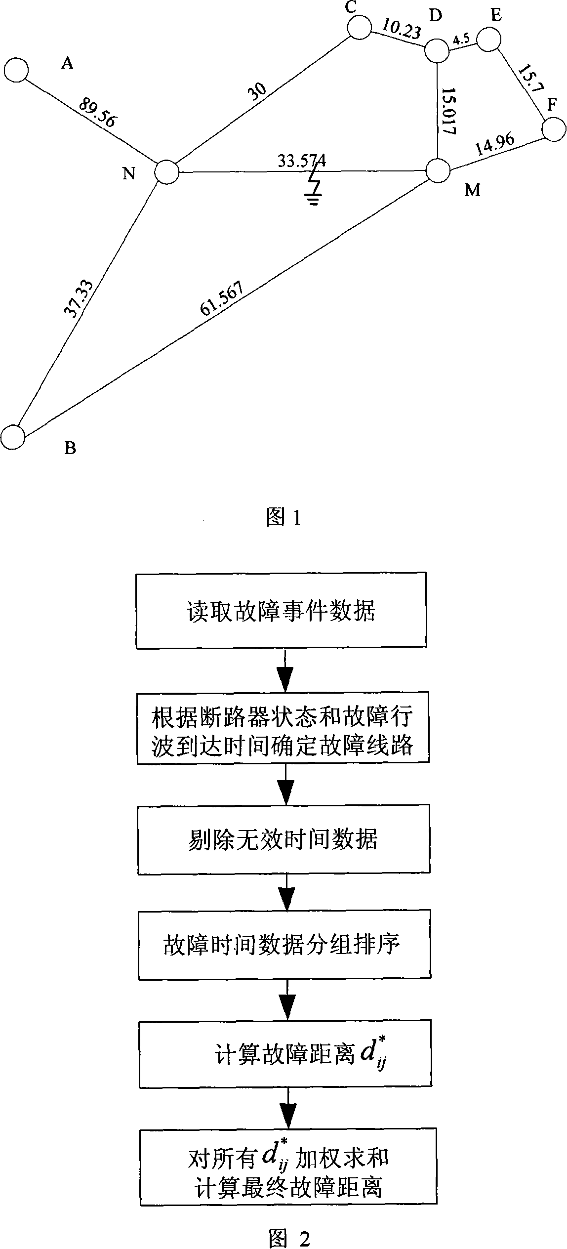
[0023] Referring to Fig. 1, Fig. 1 is to implement the simulated power grid model of the present invention, there are 8 substations in the whole power grid, fault traveling wave location device is installed in each substation, after (MN) line distance (M) station 15km place fault, can produce The traveling wave signal propagates throughout the transmission network. At this time, the positioning devices of each substation in the power grid can detect the traveling wave signal and record the arrival time of the initial traveling wave head, as shown in Table 1. The positioning device sends the arrival time of the initial traveling wave to the traveling wave positioning master station (M), and the master station (M) performs fault location according to the arrival time information of the traveling wave head of each substation.

[0024] Table 1

[0025] site name

time (μs)

site name

time (μs)

site name

time (μs)

A

B

C

371.60 ...


PUM


Abstract

The invention belongs to the field of electric power system, which relates to a fault traveling wave positioning method based on the whole electric power transmission network. The method of the invention is that all transformer substations of the electric power transmission network are provided with fault traveling wave positioning devices, and the central control room of the electric power transmission network is provided with a fault positioning main station. When the power transmission line is in fault, the positioning devices record the arrival time of the traveling wave from the transformer substations and the state of the breaker; according to the arrival time of the traveling time and the state of the breaker recorded by the positioning devices, the main station, which confirms the fault line and eliminates the ineffective time data, arranges the traveling wave time at the two sides of the fault time into two arrays, and by the two-end fault traveling wave positioning algorithm, works out the distance from the fault point to the transformer substation at the end of the fault line, after that, implements weighting summation of the fault distance, finally, gains the accurate fault position. The method of the invention eliminates the influence to the fault positioning caused by part positioning device fault, starting failure and error time record, etc., thereby greatly improving the accuracy, reliability and economic of the fault traveling wave positioning.

Description

technical field [0001] The invention belongs to the field of power systems and relates to a fault traveling wave location method based on the entire power grid. Background technique [0002] High-voltage transmission lines have long transmission distances, are exposed in the wilderness, and are mostly mountainous and hilly terrains. The rapid and precise location and search of fault points has always been an unsolved problem for the power sector, and it has also brought a heavy burden to line operation and maintenance personnel. At present, there are three main transmission line fault location methods used in power systems at home and abroad: the impedance location method based on fault recording devices, the lightning location method dedicated to lightning faults, and the GPS fault traveling wave location method. The impedance location method uses the fault recording data to calculate the fault point location of the line according to the impedance change caused by the fault...

Claims


Application Information

Patent Timeline
Patent Type & Authority Applications(China)
IPC IPC(8): H02H7/26
CPCY04S10/522Y04S10/52
Inventor 曾祥君李泽文马洪江王媛媛
Owner HNAC TECH
Why Eureka
Try Eureka