
Transmission method and transmission system of wireless relay system

A technology of wireless relay and transmission method, which is applied in the direction of radio transmission system, radio relay system, transmission system, etc., and can solve problems affecting other users' service quality, disconnection, and affecting system performance, etc.

Active Publication Date: 2008-03-12
HUAWEI TECH CO LTD
View PDF0 Cites 37 Cited by
  • Summary
  • Abstract
  • Description
  • Claims
  • Application Information

AI Technical Summary

Problems solved by technology

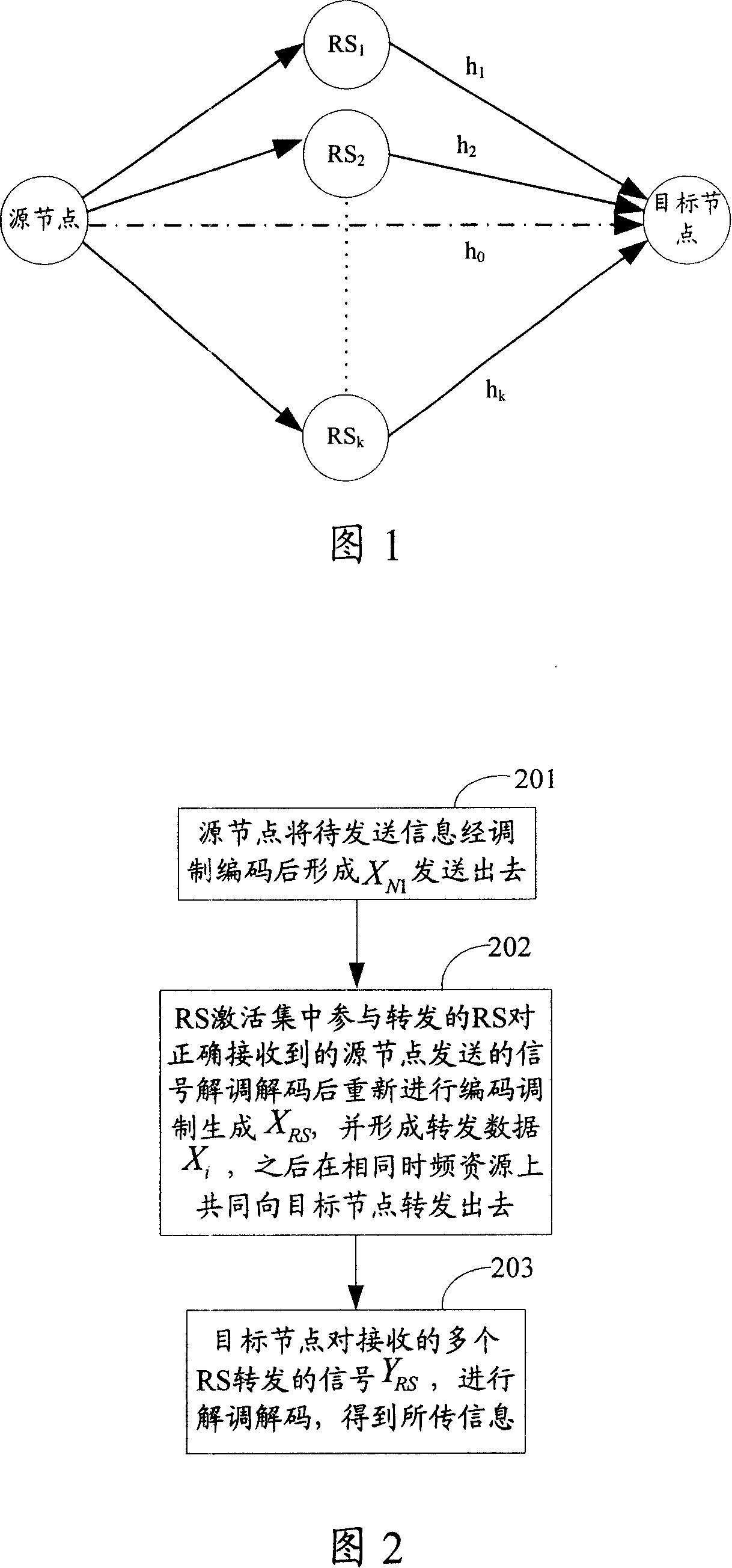
[0004] However, in a wireless communication system containing relay stations, such as the Worldwide Interoperability for Microwave Access (WiMAX) system that introduces RS, in addition to switching between different BSs, there are also RS and BS , and the switching problem between RS and RS
Since in a wireless communication system with a relay station, the MS generally selects only one RS that is most suitable for serving the current MS, the BS will re-designate an RS for the MS during relay switching. When the MS is at the junction of multiple RSs, it may not be able to find the most suitable RS to serve it, or other situations that cause the quality of the link between the current serving RS and the MS to deteriorate, will cause the service quality of the current MS to deteriorate. reduced, even broken wires and other defects
[0005] In addition, if there are several levels of relay RS forwarding between the BS and the MS, the transmission between the two nodes will involve many situations, that is, the transmission from the source node to the target node can be BS→RS, RS→RS, RS→MS, BS→MS or MS→RS, RS→RS, RS→BS, MS→BS and other situations, if only one relay RS is selected for forwarding between two nodes, the same problems, that is, it will cause the quality of service to MS to be reduced, or even disconnection and other defects
[0006] In addition, when a certain MS has multiple business flows with a large amount of data, serving it by a single RS will greatly increase the load of the RS and increase the processing burden. In severe cases, it will affect the quality of service of the RS to other users. , and even affect the overall system performance

Method used


Image

  • Transmission method and transmission system of wireless relay system
  • Transmission method and transmission system of wireless relay system
  • Transmission method and transmission system of wireless relay system

Examples


Embodiment 1

[0148] Referring to FIG. 2 , FIG. 2 is a flowchart of a first embodiment of a transmission method in a first wireless relay system in the present invention. In this embodiment, the BS or the RS with the control function maintains an active set of RSs for the target node, that is, a set of relay RSs capable of receiving signals from the source node and serving the target node. The judgment standard for entering or exiting the active set is that all relay RSs monitor the quality of the uplink signal of the source node or the target node, and judge whether the quality information of the received uplink signal meets the reporting requirements, or whether it reaches the predetermined threshold value, and if so, then Report to the BS or RS with control capability, and request to enter or exit the RS active set. For clearer description, this embodiment does not include the situation that the source node directly sends a signal to the target node. as shown in picture 2:

[0149] Ste...

Embodiment 2

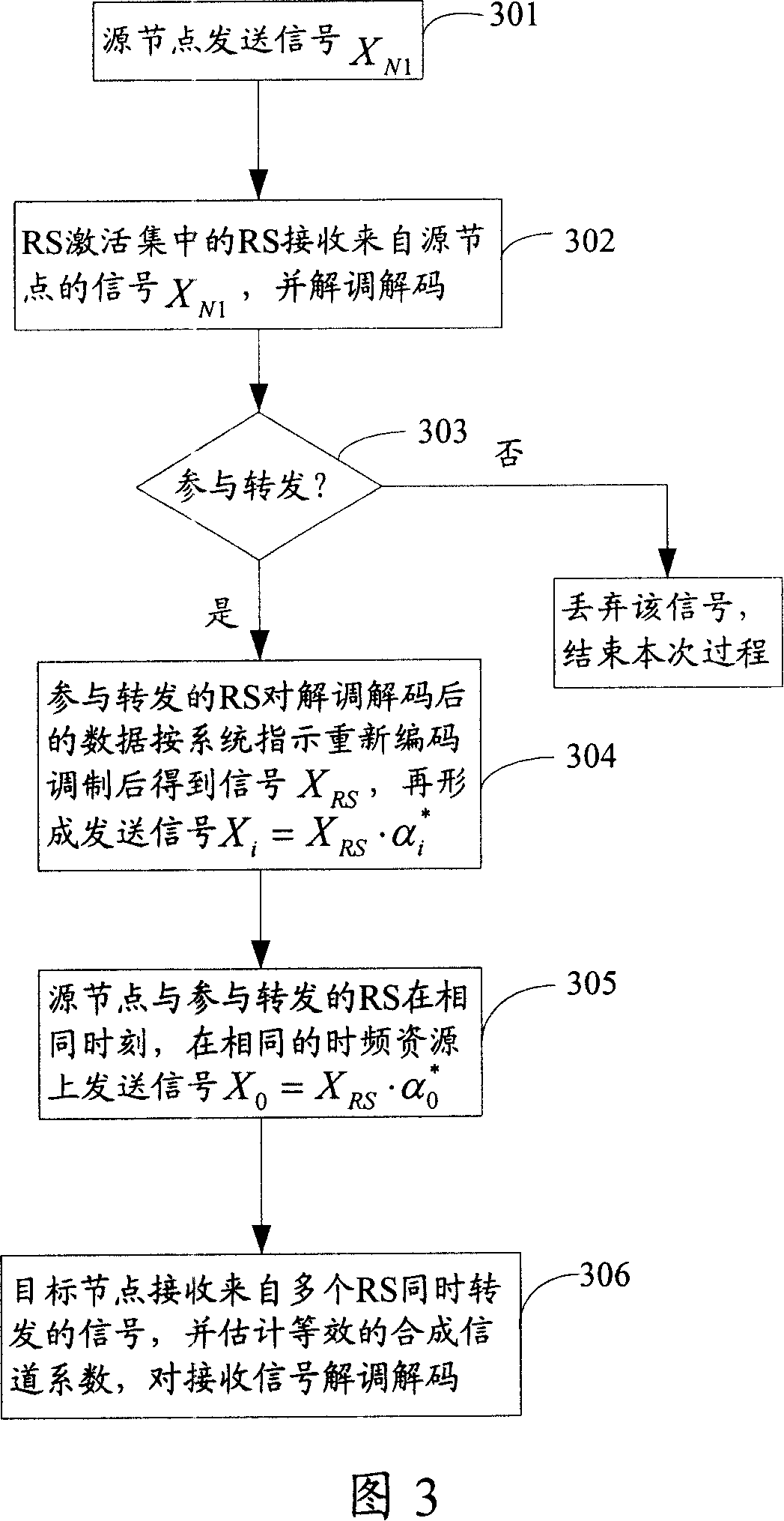
[0162] Referring to FIG. 3 , FIG. 3 is a flow chart of an embodiment of a PMPP transmission method in which strategy 1 is that the source node sends the signal twice and the target node receives the signal once. Suppose the signal sent by the source node is X N1 , generate signal X to be transmitted by RS re-encoding modulation RS , where the coding and modulation method can adopt a coding and modulation method different from that of the source node, or the same coding and modulation method as that of the source node, and the known RS i The channel coefficient to the target node is h i , where h i is with x RS Vectors with the same dimensions:

[0163] Step 301, the source node codes and modulates the signal to be transmitted to generate the transmission signal X N1 , and send it out.

[0164] Step 302, the RS in the RS active set receives the signal X from the source node N1 , and demodulate and decode.

[0165] Step 303, the RS judges whether it needs to forward the ...

Embodiment 3

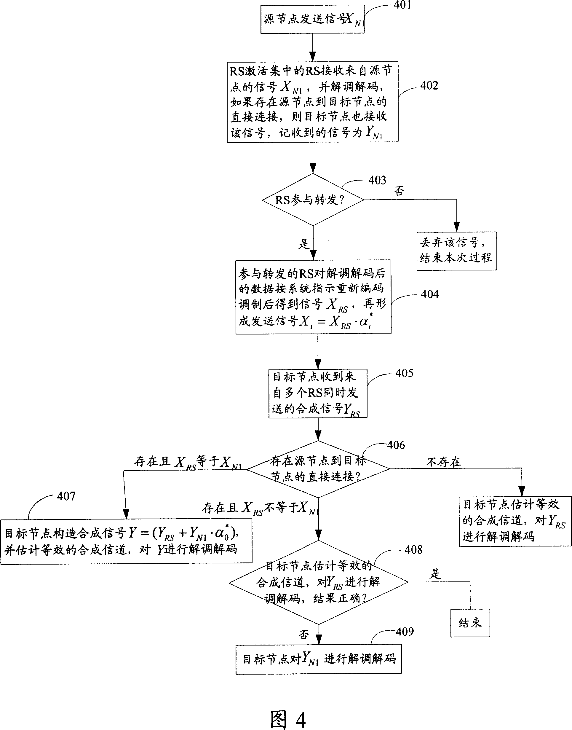
[0182] Referring to FIG. 4 , FIG. 4 is a flowchart of a PMPP transmission method in which strategy 2 is that the source node sends a signal once and the target node receives the signal twice. Suppose the signal sent by the source node is X N1 , re-coded and modulated by RS, here can adopt a different coding and modulation method from the source node, or use the same coding and modulation method as the source node, and then form the transmission signal X RS , and it is known that RS i The channel coefficient to the target node is h i , where h i is with x RS Vectors with the same dimensions:

[0183] Step 401, the source node encodes and modulates the information to be transmitted to form a transmission signal X N1 , send out.

[0184] Step 402, the RS in the RS activation set receives the signal X sent by the source node N1 , and demodulate and decode, if there is a direct data transmission from the source node to the target node, the target node also receives the signa...


PUM


Abstract

The present invention discloses a transmission method in a wireless relay system, which jointly transmits data between a source node and a destination node through a plurality of relay stations. These relay stations transmit same data on the same time frequency resources and transmit different data on varied time frequency resources. The destination node demodulates and decodes received superposed signals of the same data transmitted by the RS on the same time frequency resource. In addition, the destination node demodulates and decodes different data transmitted by the RS on the varied time frequency resource and matches demodulated and decoded data on demand and finally acquires the transmitted data. Moreover, the present invention discloses a wireless relay transmission system. The transmission method and the transmission system provided by the present invention can improve link transmission reliability, realize load balance amongst a plurality of relay stations, avoid overload of single relay station and enhance service quality for the destination node.

Description

technical field [0001] The invention relates to mobile communication technology, in particular to a transmission method and a transmission system in a wireless relay system. Background technique [0002] With the gradual improvement of people's demand for wireless communication, Broadband Wireless Access (BWA) technology is gradually becoming one of the hotspots in the current communication technology development. However, in the wireless communication system, due to the path attenuation of electromagnetic waves and the occlusion of buildings, some places become areas with low wireless communication signal strength, and the communication quality of mobile terminals located in these areas will become very poor. With the increasing demand for broadband wireless communication, the demand for wireless bandwidth becomes larger and larger, so higher and higher carrier frequencies are used in new protocols and systems, but the attenuation of radio waves increases with frequency in...

Claims


Application Information

Patent Timeline
IPC IPC(8): H04B7/14H04L69/14H04W28/00H04W28/08H04W40/22H04W52/24H04W88/04
CPCH04W52/24H04B7/2606H04W88/04H04W28/08H04B7/026H04W40/22H04W28/00H04W28/0862
Inventor 尚政张爱民王媛媛李江
Owner HUAWEI TECH CO LTD
Learn More