Cleaning tool

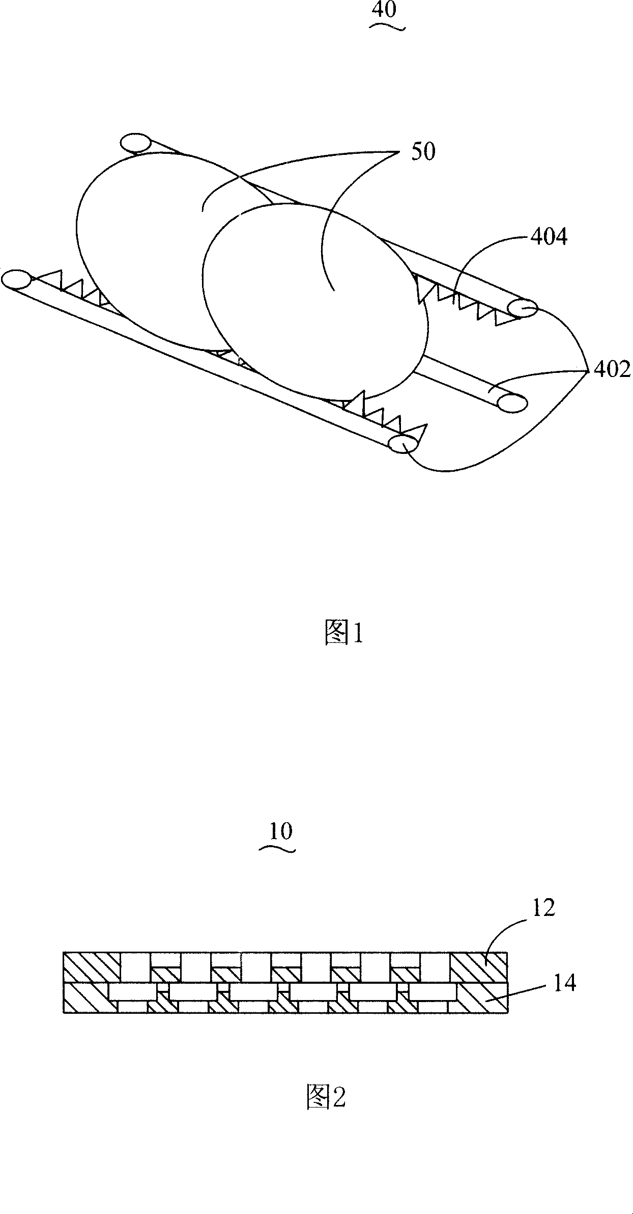
A technology for cleaning jigs and covers, applied to cleaning methods and utensils, manufacturing tools, cleaning flexible items, etc., can solve problems such as difficult to take out, the clamped part of the optical element 50 is not clean, and the optical element 50 is not easy to put in, etc. problems, to achieve the effect of improving efficiency and cleanliness

Inactive Publication Date: 2008-03-19
HONG FU JIN PRECISION IND (SHENZHEN) CO LTD +1
View PDF0 Cites 7 Cited by
  • Summary
  • Abstract
  • Description
  • Claims
  • Application Information

AI Technical Summary

Problems solved by technology

However, the thickness and depth of the V-groove 404 formed by Teflon will block the water flow, so that the clamped part of the optical element 50 will not be cleaned cleanly. Moreover, during the cleaning process, if the clamped

Method used


Image

  • Cleaning tool
  • Cleaning tool
  • Cleaning tool

Examples


Example Embodiment

[0015] The present invention will be described in further detail below in conjunction with the accompanying drawings.

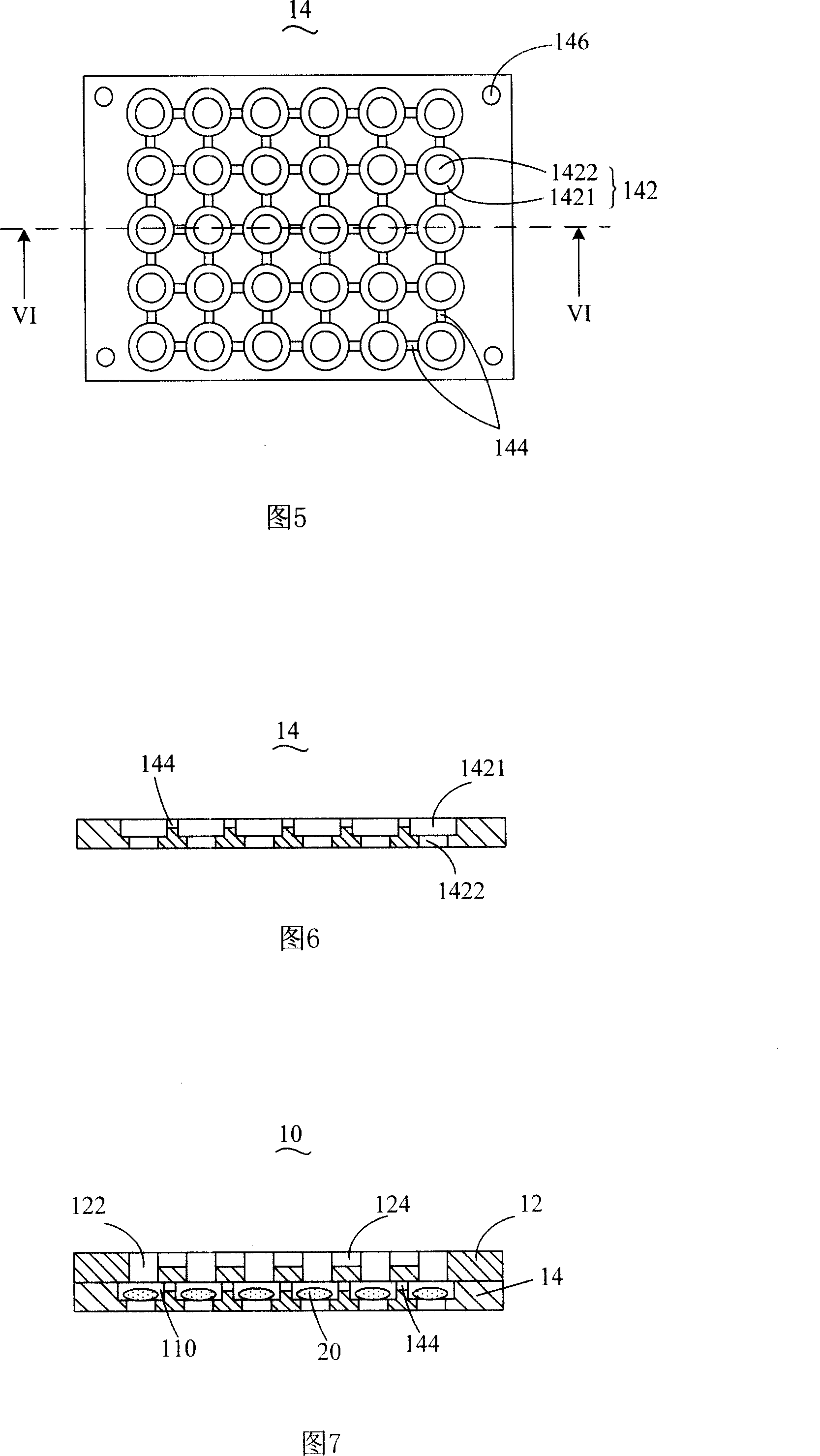
[0016] Referring to FIG. 2 , an embodiment of the present invention provides a jig 10 , the jig 10 includes a cover 12 and a body 14 . The material of the jig 10 is one of aluminum, aluminum alloy, stainless steel, titanium alloy, copper and heat-resistant engineering plastics, and the jig 10 can be manufactured using CNC (Computer Numerical Control) processing technology.

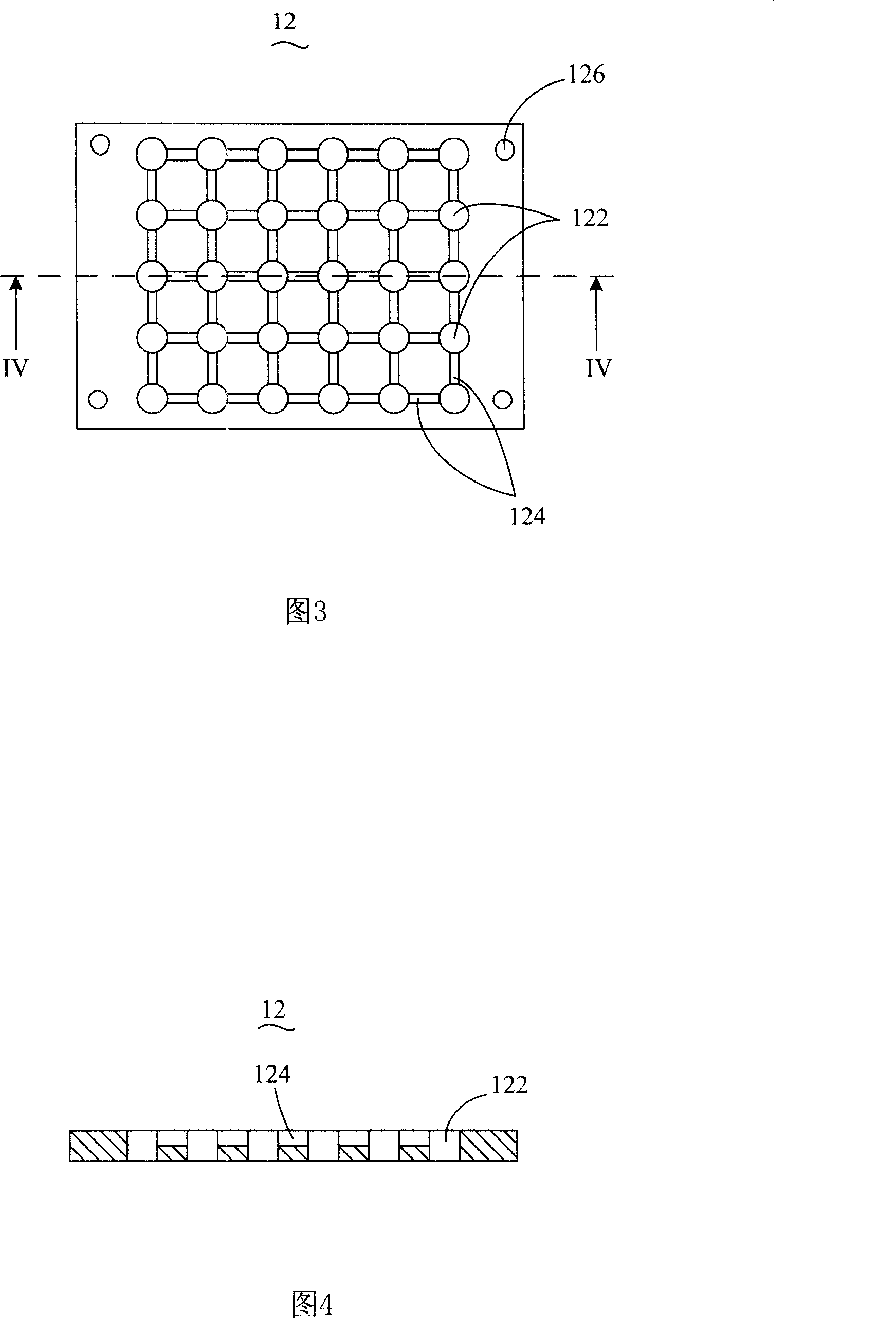
[0017] As shown in FIG. 3 and FIG. 4 , the cover body 12 is provided with a plurality of first through holes 122 and the four corners are respectively provided with first screw holes 126 . The plurality of first through holes 122 are arranged on the cover body 12 in a matrix form with a certain distance therebetween. Optionally, the first through holes 122 are distributed on the cover body 12 in a honeycomb shape.

[0018] In this embodiment, the plurality of first through holes 122 are...


PUM


Abstract

The invention provides a cleaning machine for cleaning an optical element, comprising a cover and a body. The cover is provided with at least two first clearance holes. The body is provided with at least two second clearance holes that correspond to the first clearance holes. The second clearance holes are provided with a first opening and a second opening. When the cover combines with the body, the first opening is closer to the cover than the second opening and the adjacent second clearance holes are interconnected.

Description

technical field [0001] The invention relates to a clamping device, in particular to a cleaning jig for cleaning optical elements. Background technique [0002] With the development of multimedia technology, imaging equipment such as cameras, digital cameras, and mobile phone cameras are becoming more and more popular among consumers. While people are pursuing miniaturization of cameras, digital cameras, and mobile phone cameras, the image quality of objects captured by them It shows higher requirements, that is, it is hoped that the image of the object to be photographed is clear, and the imaging quality of the object depends largely on the quality of the optical instruments in the camera. [0003] In-camera imaging modules generally include lenses, optical filters, and image sensing elements, such as charge-coupled devices or complementary oxide semiconductors. In the process of producing optical components such as lenses and optical filters, in order to achieve a high deg...

Claims


Application Information

Patent Timeline
IPC IPC(8): B08B13/00B08B11/02B08B3/04B25B11/00
Inventor 董才士
Owner HONG FU JIN PRECISION IND (SHENZHEN) CO LTD
Why Eureka
Try Eureka