Intrmittent pulse electrolysis

a pulse electrolysis and pulse technology, applied in pulse technique, generating/distributing signals, electric circuits, etc., can solve the problems of limited power applicable for a certain volume of the electrolysis bath, difficulty in increasing the input power of a constant volume electrochemical cell without reducing the electrolysis efficiency, etc., to achieve the effect of enhancing the performance of an internal combustion engin

Inactive Publication Date: 2012-07-12
DARREL FLETCHER
View PDF2 Cites 13 Cited by
  • Summary
  • Abstract
  • Description
  • Claims
  • Application Information

AI Technical Summary

Benefits of technology

[0008]The present invention enables a fuel comprised of hydrogen and/or oxygen gases to be generated by electrolysis of water at such a rate that it can enhance performance of an internal combustion engine. It achieves this result by use of a novel pulse generator in conjunction with at least one electrolytic cell. According to the present invention, there is provided a pulse generator comprising four primary components, namely, 1) a wave generator connected to a power source, the wave generator having an output signal, 2) a de multiplexer (DeMux) having a single in

Problems solved by technology

It is therefore difficult to increase the input power for a constant volume electrochemical cell without reduction in electroly

Method used


Image

  • Intrmittent pulse electrolysis
  • Intrmittent pulse electrolysis
  • Intrmittent pulse electrolysis

Examples


example 1

Hydrogen vs. Hydrogen and Oxygen Fed into Vehicle Equipped with 7.3 Liter Duramax Diesel Engine

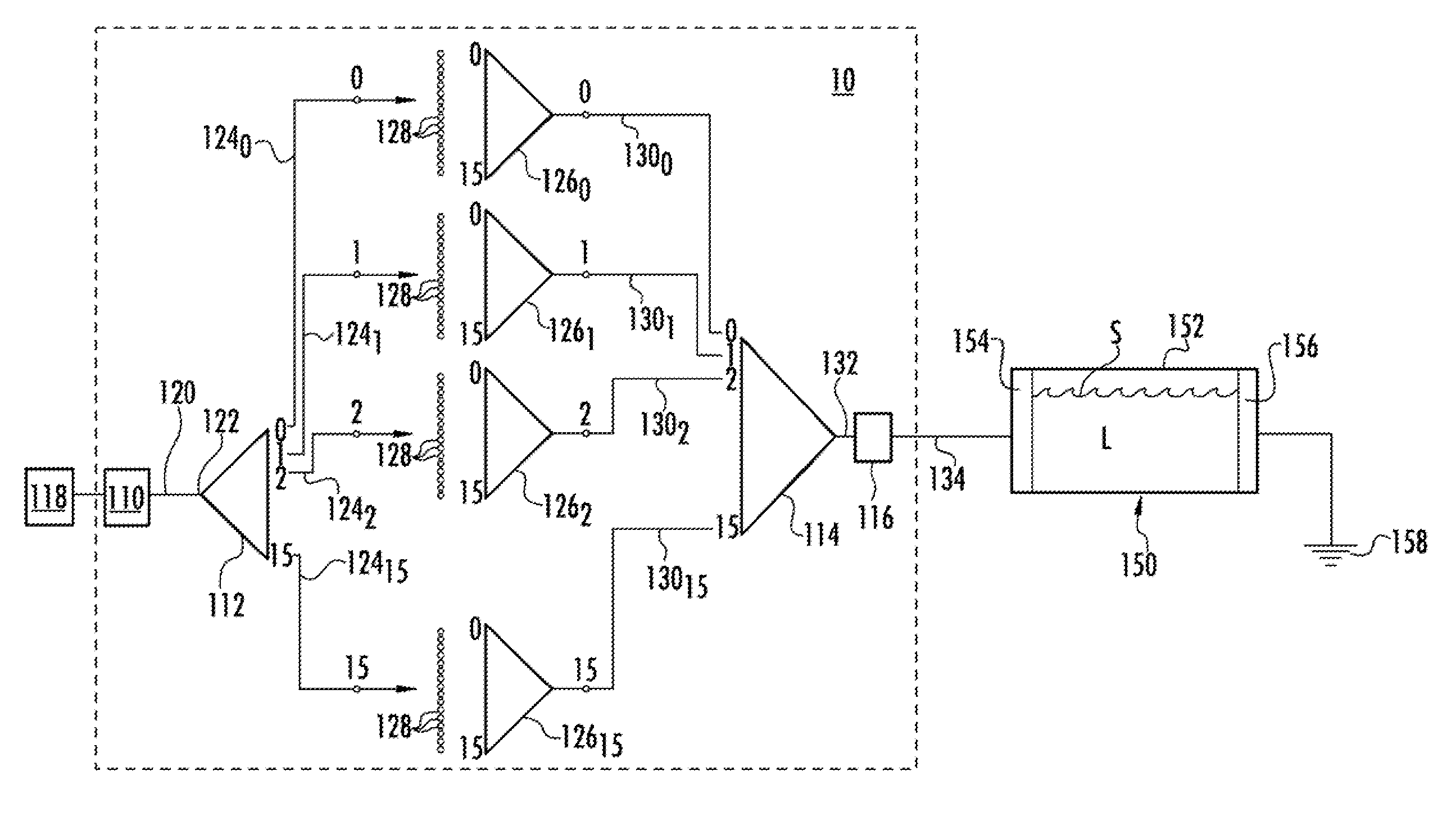
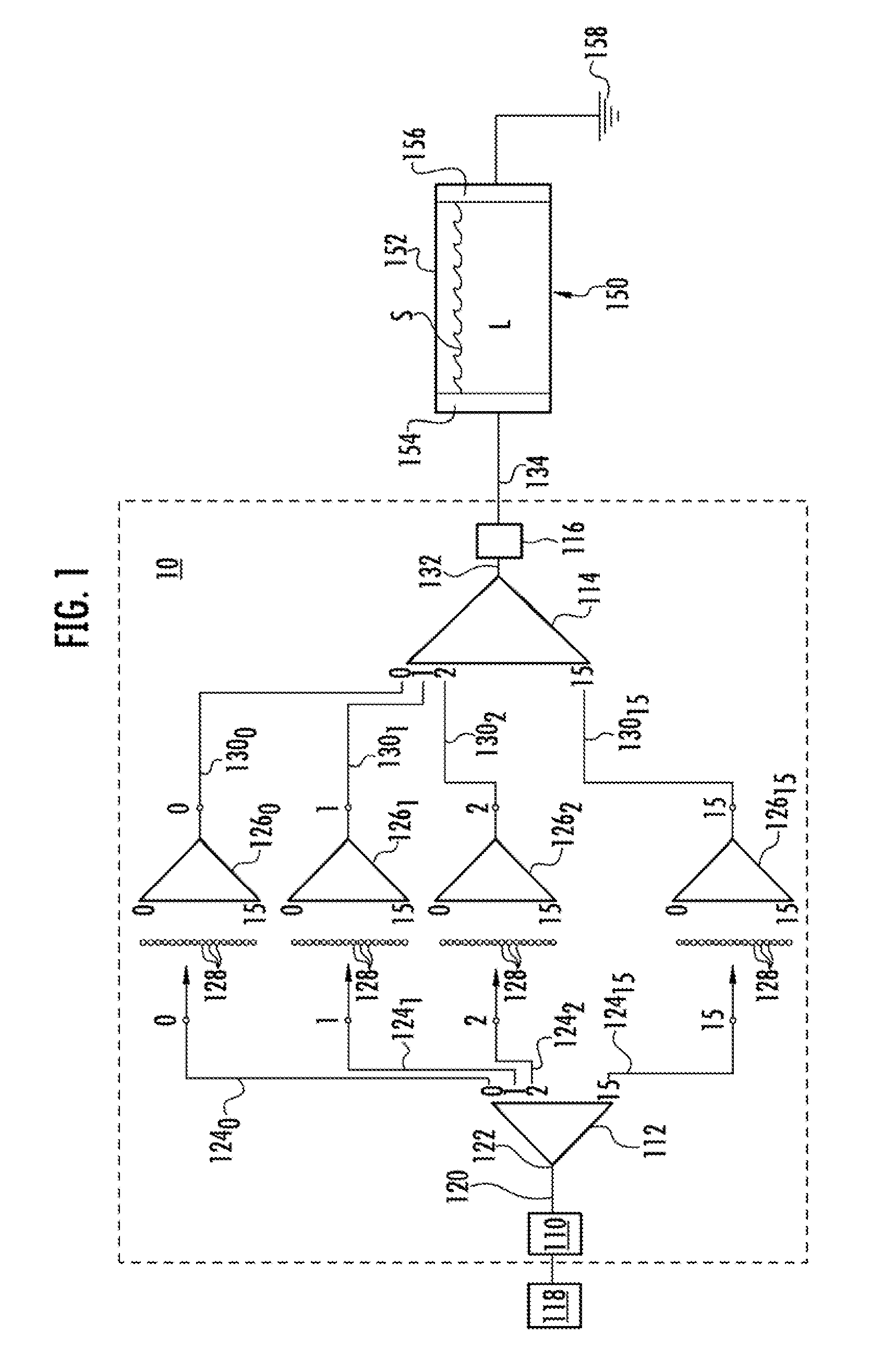
[0024]An electrolytic fluid F is interposed within housing 152 of electrolytic cell 150 in sufficient volume to substantially cover the surfaces of anode 154 and cathode 156. Typically, the electrolytic fluid may be either water, potassium hydroxide or a similar compound capable of generating free oxygen and hydrogen ions as a result of an electrolytic reaction. The volume of fluid F will generally not entirely fill housing space 18 and a space S will typically be left at the top portion thereof. The subject intermittent pulse generator 10 is set to deliver to the electrolytic cell 150 a train of ultra-short pulses, the rate of which is limited only by available technology, with 0 to 16 different time delay settings per each sixteen channel cycle. In a rotational motor with 16 active channels per crank rotation equals a timing baseline of 22.5 degrees per crank rotation. Sixteen channels t...

example 2

Hydrogen vs. Hydrogen and Oxygen Mix Fed into Vehicle Equipped with 6.7 Liter Cummins Diesel Engine

[0029]Using the same setup and protocol described above, the optimal flow rates of Hydrogen and then a Hydrogen / Oxygen mixture into a 2007 Dodge 3500 truck equipped with a 6.7 liter Cummins diesel were determined. Engine performance without the subject apparatus was measured at 350 HP and 650 Ft / Lbs of torque on the initial run for testing of Peak HP and Torque on the Mustang Dynamometer, which is consistent with the published results for this vehicle engine, make and model.

[0030]Injection of liberated Hydrogen only: The tuck was ran under a steady state condition; @ 1500 rpms under a 5% load “approximately 50 mph”, where the Hydrogen level was increased at a rate of 0.5 Liters a minute, every 45-seconds, using a Victor 0-8 LPM dial regulator gauge. This extended load testing went from 0.5 to 6 liters a minute.

[0031]Injection of liberated Hydrogen and Oxygen mix (2 parts Hydrogen to 1 ...


PUM

PropertyMeasurementUnit
Timeaaaaaaaaaa
Widthaaaaaaaaaa
Resolution enthalpyaaaaaaaaaa

Abstract

A pulse generator includes a wave generator connected to a power source, the wave generator having an output signal; a de-multiplexer having a single input for receiving the output signal of the wave generator and splitting the signal into a plurality of channels carrying corresponding DeMux output signals; and a multiplexer electrically connected to each of the DeMux output signals and including means for alternately advancing or retarding the time interval between pulses of each the DeMux output signals and for combining at least two of the advanced or retarded output signals together and outputting the at least two advanced or retarded output signals as a single circuit output signal having a diverse pulse train. Pulse control means for controlling at least one of the pulse width and pulse amplitude of the circuit output signal is also provided.

Description

RELATED APPLICATION[0001]This application claims the benefit of U.S. Provisional Application No. 61 / 430,719 filed Jan. 7, 2011 and entitled, Intermittent Pulse Electrolysis.FIELD OF THE INVENTION[0002]The subject invention relates generally to an apparatus and method for decomposing chemical compounds by means of electrical energy and, more specifically to such an apparatus and method for obtaining the release of hydrogen and oxygen from water by means of delivering an intermittent pulsed signal to at least one electrolytic cell.BACKGROUND OF THE INVENTION[0003]Numerous processes have been proposed for separating a water molecule into its elemental hydrogen and oxygen components. Electrolysis is one such process. In electrolysis, a potential difference is applied between an anode and a cathode in contact with an electrolytic conductor to produce an electric current through the electrolytic conductor.[0004]In the conventional DC electrolysis of water, hydrogen is generated as a resul...

Claims


Application Information

Patent Timeline
IPC IPC(8): C25B15/02H03K3/00C25B9/04
CPCC25B1/04Y02E60/366H03K2005/00052H03K5/13Y02E60/36
Inventor DARREL, FLETCHER
Owner DARREL FLETCHER
Why Eureka
Try Eureka