
Dynamic compensation hydraulic pressure servo valve null shift method

A hydraulic servo and dynamic compensation technology, applied in servo motor components, fluid pressure actuating devices, mechanical equipment, etc., can solve the static error changes, can not take into account the system dynamic response speed is fast, static error is small, can not be fundamentally reduced Static error and other problems, to achieve the effect of improving the accuracy of position control

Inactive Publication Date: 2008-03-19
NORTHEASTERN UNIV LIAONING
View PDF0 Cites 12 Cited by
  • Summary
  • Abstract
  • Description
  • Claims
  • Application Information

AI Technical Summary

Problems solved by technology

This can only eliminate zero drift for a period of time, but as the hydraulic system operates, the zero drift will change with site conditions, and the static error will change accordingly
This method cannot fundamentally reduce the static error
[0009] Both of these methods have defects, and cannot take into account the requirements of fast dynamic response and small static error of the system.

Method used


Image

  • Dynamic compensation hydraulic pressure servo valve null shift method
  • Dynamic compensation hydraulic pressure servo valve null shift method
  • Dynamic compensation hydraulic pressure servo valve null shift method

Examples


Embodiment Construction

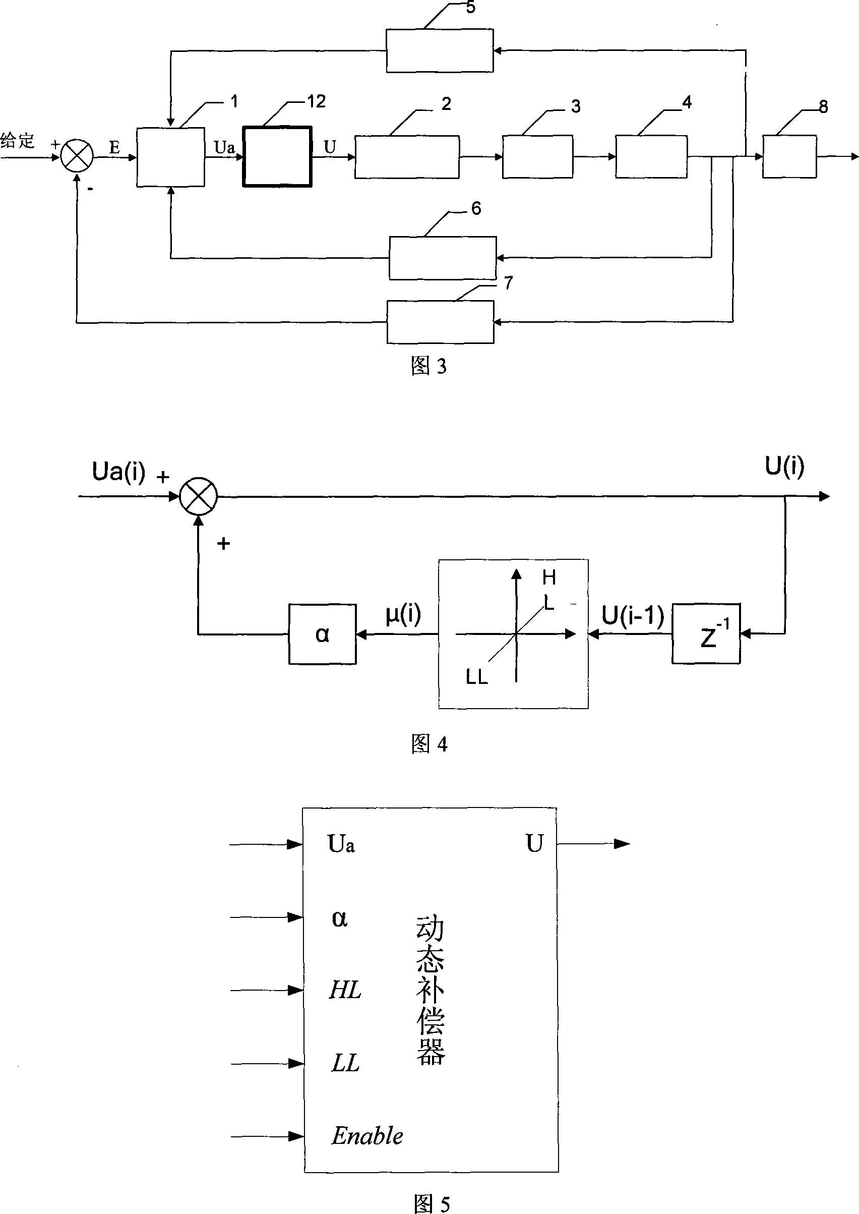
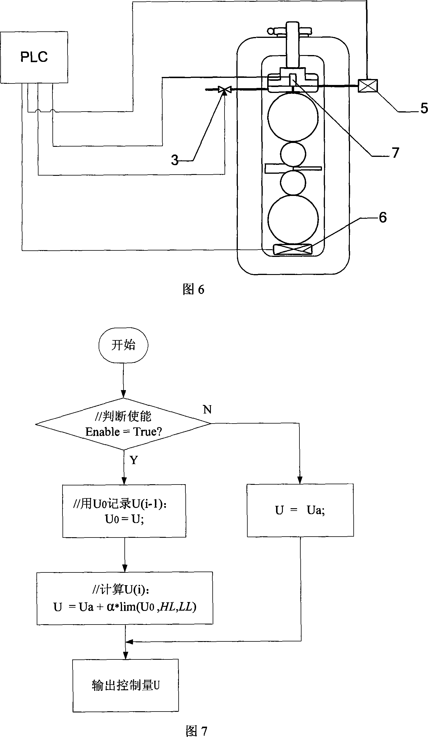
[0031] As shown in Fig. 3, the present invention comprises HAPC adjuster, dynamic compensator, servo amplifier, servo valve, hydraulic cylinder and are connected successively; Be connected with oil pressure sensor and pressure sensor between hydraulic cylinder and HAPC adjuster; There is a displacement sensor connected with the HAPC regulator. According to the deviation between the given position and the measured value, the HAPC regulator controls the opening of the servo valve to perform closed-loop adjustment of the position of the hydraulic cylinder. Among them: the program of the dynamic compensator is shown in Figure 7, the principle of the dynamic compensator is shown in Figure 4, and the steps of the dynamic compensation algorithm used are as follows:

[0032] The algorithm formula is: U(i)=U a (i)+αμ(i)=U a (i)+αlim(U(i-1), HL, LL) (1)

[0033] where U a (i) is the output value of the HAPC regulator at the ith moment, U(i) is the output value of the dynamic compens...


PUM


Abstract

A dynamic compensation hydraulic pressure servo valve zero drift method is disclosed. A displacement sensor, an oil pressure sensor, and a servo valve are arranged on a rolling machine hydraulic cylinder, and the displacement detection and the oil pressure signal of the hydraulic cylinder are read through a PLC high speed gathering module, to calculate the zero drift compensation amount of the hydraulic pressure servo valve, and to control the opening degree of the servo valve to perform the closed loop adjustment of the hydraulic cylinder position. The positive effect of the invention can be used for any HAPC algorithm, can not only guarantee the response speed of the original system, but aslo greatly enhance the static control precision of the original system.

Description

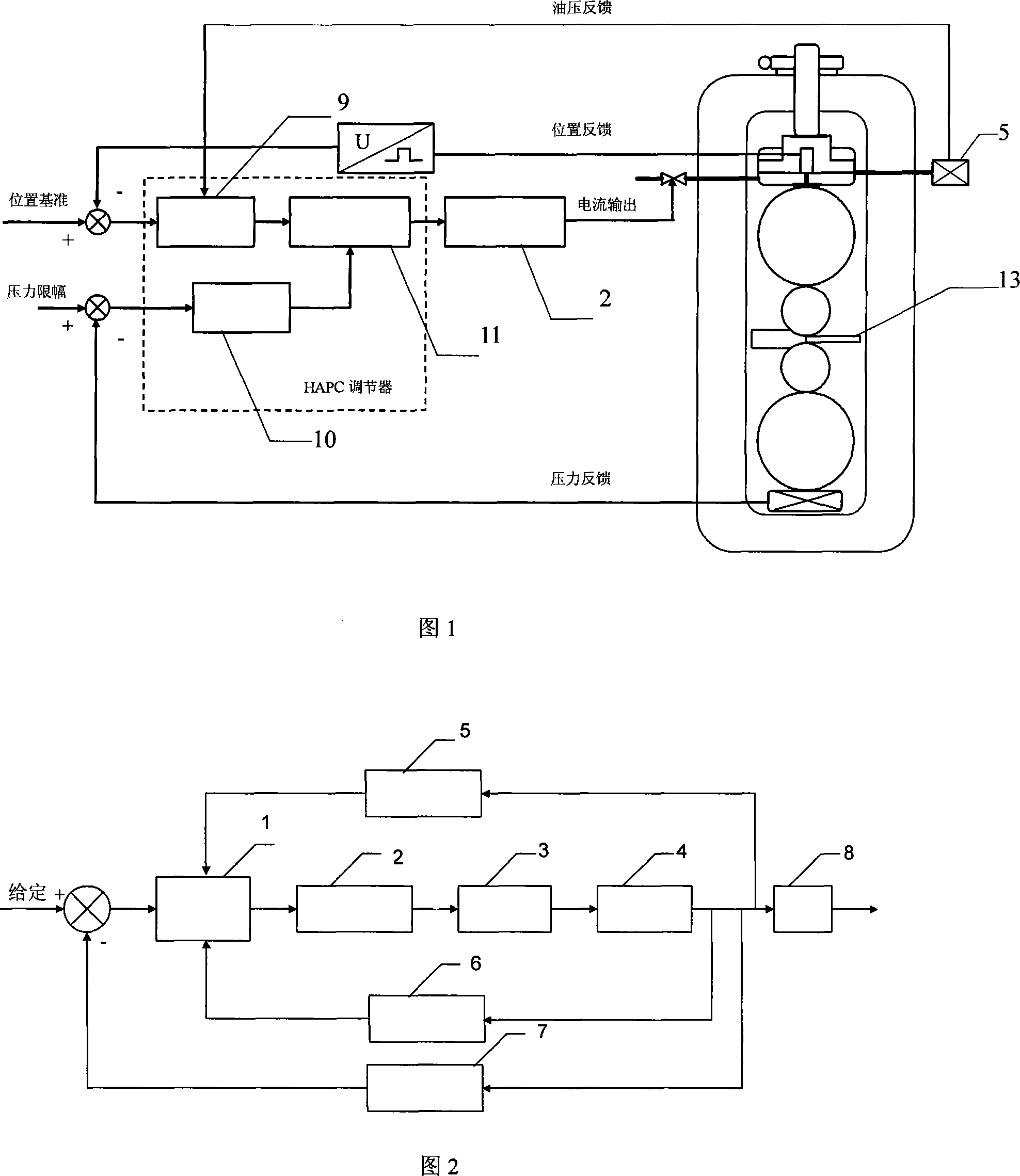
technical field [0001] The invention belongs to the technical field of hydraulic cylinder automatic position control (HAPC) in strip rolling, and in particular relates to a method for dynamically compensating the zero drift of a hydraulic servo valve. Background technique [0002] The HAPC regulator compares the actual hydraulic cylinder position measured by the displacement sensor with the given position value, the deviation signal is calculated by the regulator, the D / A output is calculated, and after the power amplifier is amplified, the opening of the servo valve is adjusted to control the hydraulic cylinder. The piston moves to complete the closed-loop control of the hydraulic cylinder position. The principle of HAPC control system is shown in Figure 1, and the block diagram of HAPC control system is shown in Figure 2. [0003] The HAPC regulator in Figure 2 generally uses a PID controller. Considering that the rolling mill system has extremely high requirements for th...

Claims


Application Information

Patent Timeline
Patent Type & Authority Applications(China)
IPC IPC(8): F15B13/16
Inventor 孙涛张殿华王君
Owner NORTHEASTERN UNIV LIAONING
Learn More