Interferometer spectrometer flat field method

A technology of interference imaging and spectrometer, applied in the direction of interference spectroscopy, using multiple reflections to generate spectra, spectrometry/spectrophotometry/monochromator, etc., can solve the problems of comprehensiveness and poor effect, and achieve comprehensive correction, Eliminate system errors and improve the effect of correction

Inactive Publication Date: 2008-03-19
XI'AN INST OF OPTICS & FINE MECHANICS - CHINESE ACAD OF SCI
View PDF0 Cites 17 Cited by
  • Summary
  • Abstract
  • Description
  • Claims
  • Application Information

AI Technical Summary

Problems solved by technology

[0004] The purpose of the present invention is to provide a flat-field method for an interference imaging spectromete...

Method used


Image

  • Interferometer spectrometer flat field method
  • Interferometer spectrometer flat field method
  • Interferometer spectrometer flat field method

Examples


Embodiment Construction

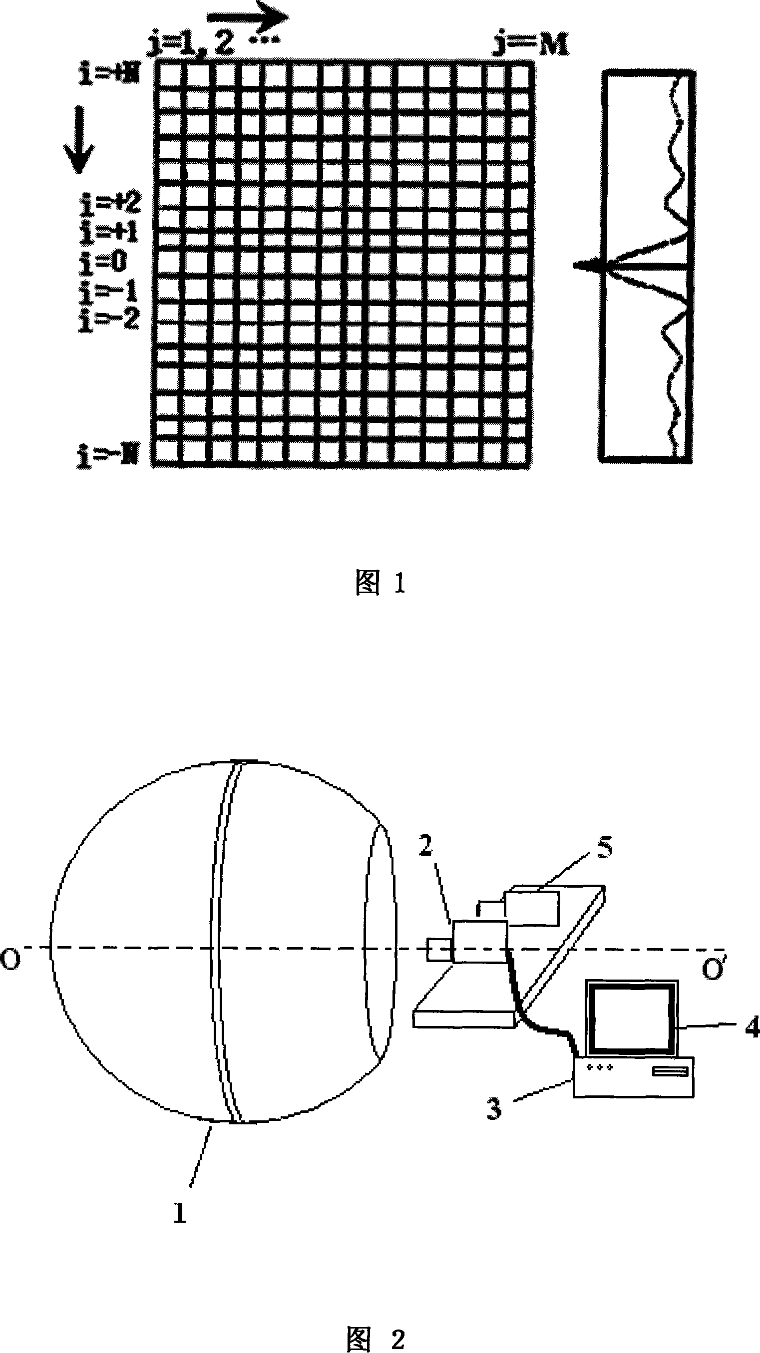
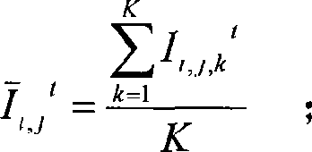
[0041] Referring to Fig. 1, the present invention proposes the "row" or "column" of the CCD matrix to balance field correction method. The spatial direction, that is, the row direction is i=0, ±1, ±2...±N horizontally arranged rows; the interferogram direction, that is, the column direction is j=1, 2...M vertically arranged columns. It mainly corrects the inconsistency of the response between CCD pixels of the whole machine assembled by optics, precision structure, area array CCD detector and electronics, and provides a two-dimensional flat field correction matrix for the instrument to eliminate the system of the instrument. sex error. The experimental correction shows that it has a good effect.

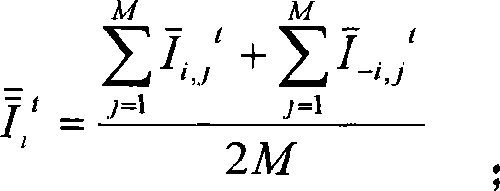
[0042] Principle of the present invention: i=0 is a line occupied by zero optical path difference, the spatial direction is the row direction i=±1,±2... is each row arranged horizontally, and the flat-field light source is a uniform surface light source, then the output image of th...


PUM


Abstract

The invention relates to a flat field method for an imaging interferometer. The optical axis of the flat field imaging interferometer is collimated to the center of the opening of the flat field light source, the interferometry image data output by the flat field imaging interferometer is acquired by an image acquisition card, and sent to the computer to processing, the flat field correction matrix is calculated, the flat field uncertainty is analyzed, and the flat field correction matrix is acquired. The invention solves the technical problem that the allsidedness and the effect of the correction are correspondingly poor in the technical background. The invention is mainly utilized on the flat field of an entire spatial modulation imaging interferometer to eliminate the system error, and the inconsistence of the response between pixels can be corrected at one-time. The invention is also suitable for the flat field of the imaging interferometer embarked on a plane or a satellite during the flying processing by utilizing the ground standard radiation field.

Description

technical field [0001] The invention relates to a method for eliminating system errors of an interference imaging spectrometer, in particular to a field flattening method for a space modulation type interference imaging spectrometer. technical background [0002] The image information output by the interference imaging spectrometer is interference fringes, which is different from ordinary cameras. Therefore, the flat-field principle and method of ordinary cameras are not suitable for interference imaging spectrometers. [0003] At present, the methods for correcting the inconsistency between the pixels of the CCD detector and the electronic part are relatively poor in the comprehensiveness and effect of the correction. Especially when the optical system has a large field of view or even has vignetting, the disadvantages are more prominent. Contents of the invention [0004] The purpose of the present invention is to provide a flat field method for an interference imaging...

Claims


Application Information

Patent Timeline
IPC IPC(8): G01J3/26G01J3/45G01J3/10
Inventor 赵葆常杨建峰薛彬乔卫东邱跃洪
Owner XI'AN INST OF OPTICS & FINE MECHANICS - CHINESE ACAD OF SCI
Why Eureka
Try Eureka