Method for manufacturing optical element

A processing method and technology for optical components, applied in optical components, optics, metal processing equipment, etc., can solve problems such as increased production time, inconsistent processing accuracy and processing errors of lenses and filters, unfavorable productivity and machine utilization, etc.

Inactive Publication Date: 2008-03-19
HONG FU JIN PRECISION IND (SHENZHEN) CO LTD +1
View PDF0 Cites 15 Cited by
  • Summary
  • Abstract
  • Description
  • Claims
  • Application Information

AI Technical Summary

Problems solved by technology

First of all, lenses and filters are produced separately, and different processing machines may cause inconsistencies in the processing accuracy and processing errors of lenses and filters, resulting in low assembly accuracy when assembling lens modules
Secondly, the centering and edging of the lens and the rounding of the filter need to be processed separately, that is, during the processing, the lens and the filter need to be put on the machine, fixed, processed, and removed from the machine, which increases the production cost. time, which is not conducive to increasing productivity and machine utilization

Method used


Image

  • Method for manufacturing optical element
  • Method for manufacturing optical element
  • Method for manufacturing optical element

Examples


Embodiment 1

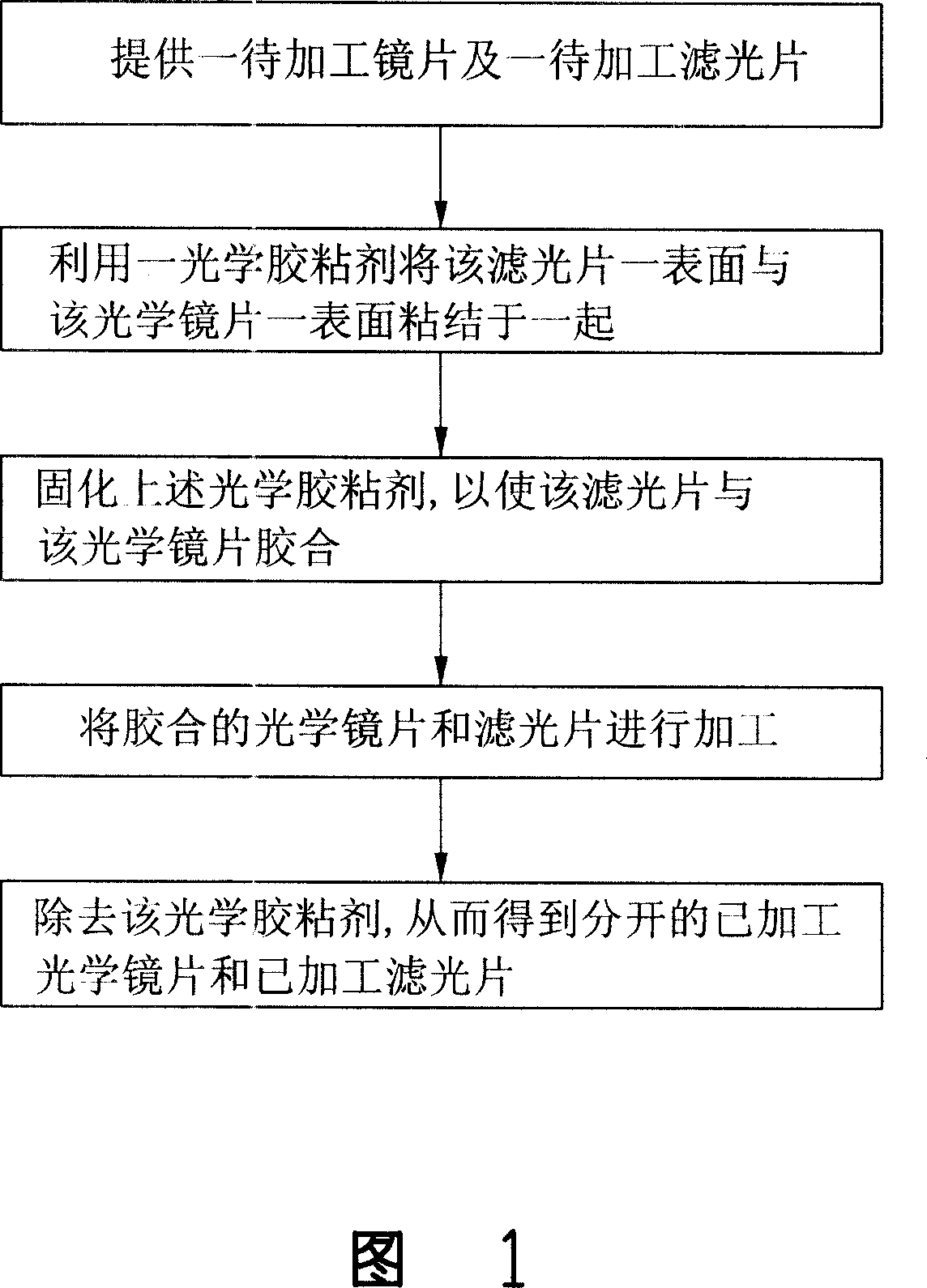
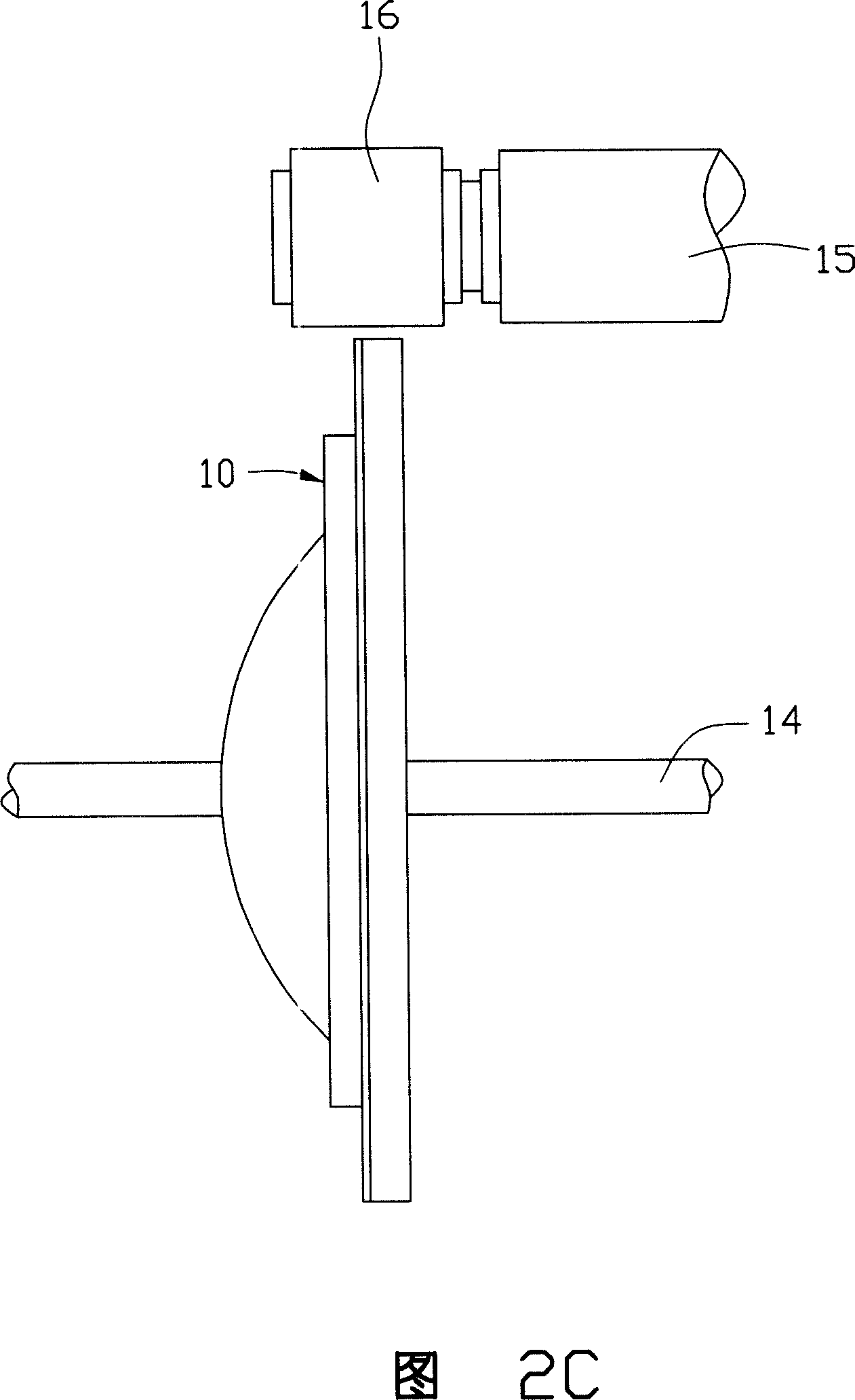
[0038] Please refer to Figures 2A-2D, the glass lens and optical filter processing method provided by Embodiment 1 of the present invention is as follows:

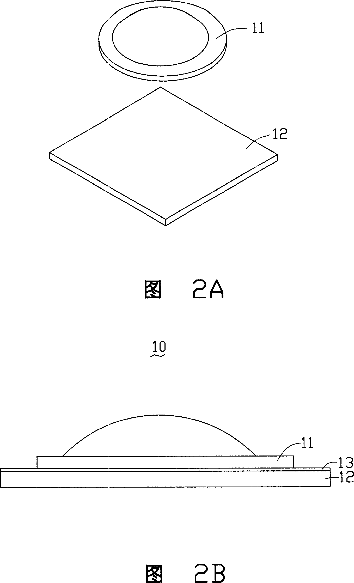
[0039] The first step, as shown in FIG. 2A , provides a glass lens 11 to be centered and edged and a filter 12 to be rounded.

[0040] In this embodiment, after material selection, cutting, rounding, forming, coarse and fine grinding, polishing and other processes, the glass body is made into the glass lens 11 to be centered and edged, and the filter is made into the rounded filter lens 11 through the material selection and cutting processes. slice 12.

[0041] In the second step, as shown in FIG. 2B , a surface of the optical filter 12 and a surface of the glass lens 11 are bonded together with a water-soluble thermosetting adhesive 13 .

[0042] In this embodiment, the glass lens 11 and the optical filter 12 are bonded together with a water-soluble thermosetting glue 13 , for example, the glue 13 may be a water-soluble ...

Embodiment 2

[0050] Please refer to Figures 3A to 3E, the glass lens and optical filter processing method provided by Embodiment 2 of the present invention is as follows:

[0051] The first step, as shown in FIG. 3A , is to provide a glass lens 21 to be centered and edged and a mother filter 22 .

[0052] Through the processes of material selection, cutting, rounding, forming, coarse and fine grinding, and polishing, a plurality of glass lenses 21 to be centered and edged are manufactured. And a filter master 22 is provided for adhering a plurality of optical lenses 21 to be centered and edged thereon. The filter mother sheet 22 can be cut into a plurality of rounded filters 24 .

[0053] In the second step, as shown in FIG. 3B , a surface of the optical filter 22 and a surface of the glass lens 21 are bonded together with a water-soluble ultraviolet curing glue 23 .

[0054] In this embodiment, the glass lens 21 and the optical filter master piece 22 are bonded together with a water-sol...


PUM


Abstract

The present invention provides an optical component processing method, and includes the following procedures: providing an optical lens needing to be processed and a light filtering piece needing to be processed, using an optical adhesive to bond a surface of the light filtering piece and a surface of the optical lens together; solidifying the above optical adhesive to bond the light filtering piece and the optical lens together; processing the bonded optical lens and the light filtering piece; removing the optical adhesive and then obtaining the processed optical lens and the processed light filtering piece which are separated. In the technical proposal, the processing precisions of the optical lens and the light filtering piece are essentially consistent, that can facilitate to improve the assembly precision, to reduce the production time, and to improve the yield.

Description

technical field [0001] The invention relates to a processing method for an optical element, in particular to a processing method for an optical element related to a lens module. Background technique [0002] The processing process of optical components usually includes material selection, cutting, rounding, forming, coarse and fine grinding, polishing and centering and edging. The cutting process refers to the process of cutting out the processing body of an appropriate size from the entire optical glass body after material selection. Rounding, also known as rounding, refers to the process of grinding the cut body into a circular shape with a grinding wheel. Forming refers to the process of forming a spherical or aspherical surface with a predetermined radius of curvature by grinding or molding the green body after rounding. The purpose of the rough grinding and polishing process is to further refine the surface of the formed optical element, such as eliminating knife line...

Claims


Application Information

Patent Timeline
IPC IPC(8): G02B7/00B24B9/14C03B33/04
Inventor 李欣和
Owner HONG FU JIN PRECISION IND (SHENZHEN) CO LTD
Why Eureka
Try Eureka