Coupling inductance dual-buck full bridge inverter

A technology of full-bridge inverters and coupled inductors, which is applied to electrical components, AC power input conversion to DC power output, and output power conversion devices. It can solve problems such as reducing system reliability and bridge arm switch tubes. Achieve the effect of optimizing design, improving conversion efficiency and improving reliability

Inactive Publication Date: 2008-03-19
NANJING UNIV OF AERONAUTICS & ASTRONAUTICS
View PDF0 Cites 32 Cited by
  • Summary
  • Abstract
  • Description
  • Claims
  • Application Information

AI Technical Summary

Problems solved by technology

However, the full bridge has a bridge arm switch tube thr

Method used


Image

  • Coupling inductance dual-buck full bridge inverter
  • Coupling inductance dual-buck full bridge inverter
  • Coupling inductance dual-buck full bridge inverter

Examples


Embodiment Construction

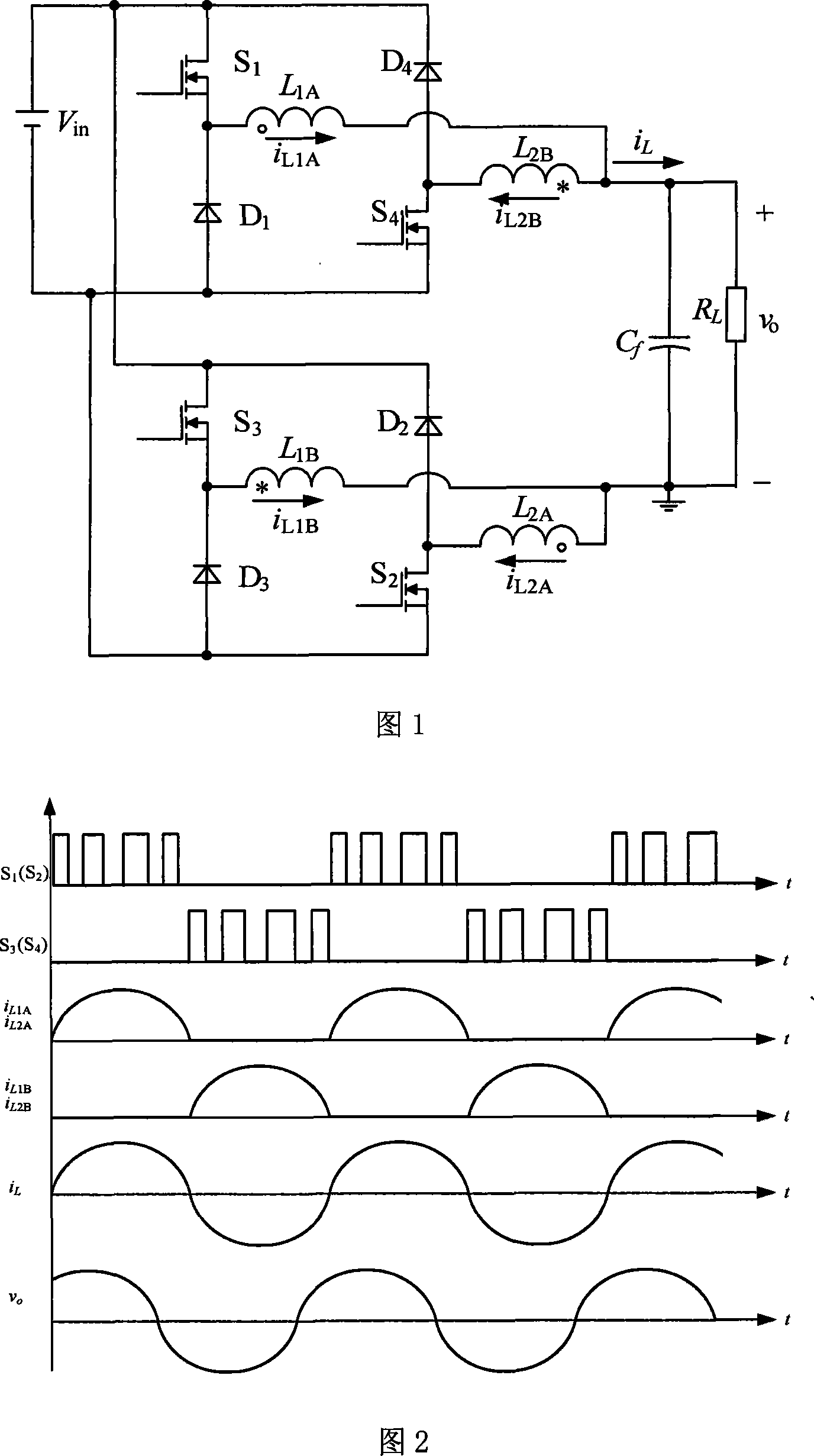
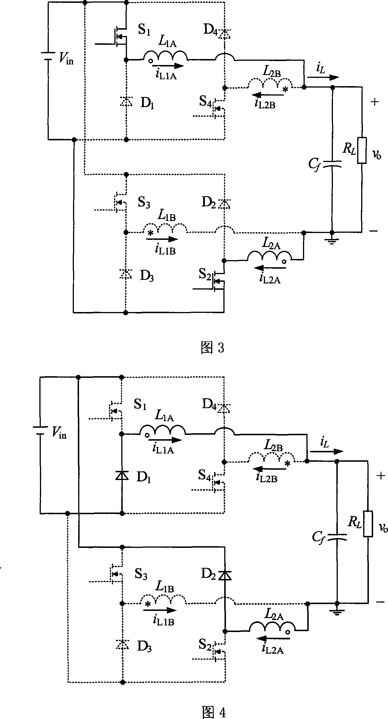
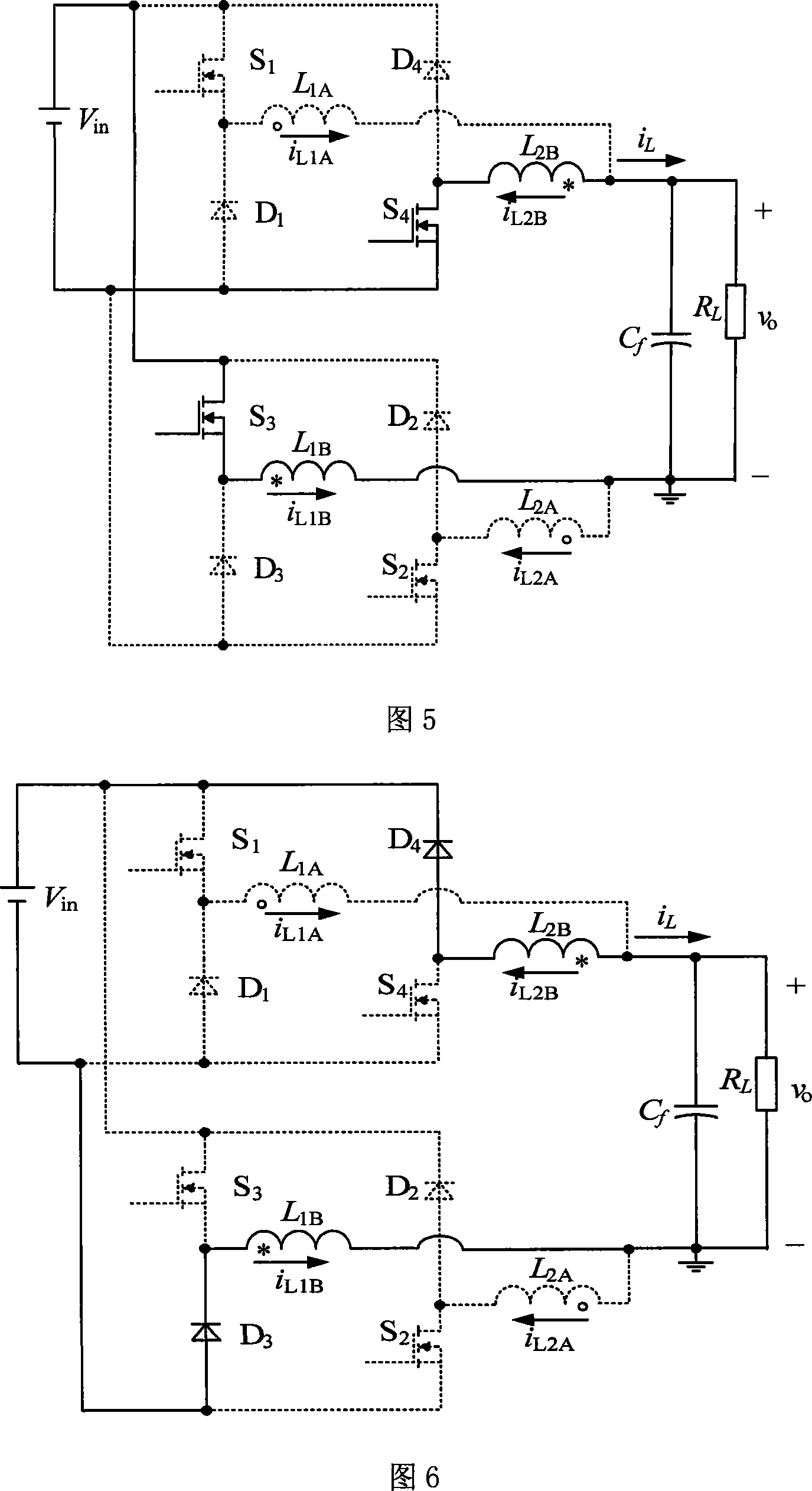
[0011] The specific embodiment of the present invention will be described according to the accompanying drawings. It can be seen from FIG. 1 that the coupled inductor double-step-down full-bridge inverter of the present invention is composed of two step-down circuits. When the sum of the filter capacitor current and the load current is positive (the reference direction is shown in Figure 1), the power supply V in , power switch tube S 1 and S 2 , coupling inductor A, filter capacitor C f and load R L , and the freewheeling diode D 1 and D 2 Form a step-down circuit; when the sum of the filter capacitor current and the load current is negative, the power supply V in , power switch tube S 3 and S 4 , coupling inductor B, filter capacitor C f and load R L , and the freewheeling diode D 3 and D 4 Form another step-down circuit.

[0012] The control method is as follows: define the sum of the output filter capacitor current and the load current as i L , the reference ...


PUM


Abstract

The invention relates to a coupling inductor dual buck full-bridge inverter, belonging to an electronic inverter. The inverter is composed of two buck circuits. One buck circuit comprises a first power switching tube (S1), a second power switching tube (S2), a first flywheel diode (D1), a second flywheel diode (D2), a first coupling inductor primary winding (L1A), a first coupling inductor secondary winding (L2A), a filtering capacitor (Cf) and a load (RL); and the other buck circuit comprises a third power switching tube (S3), a fourth power switching tube (S4), a third flywheel diode (D3), a fourth flywheel diode (D4), a second coupling inductor primary winding (L1B), a second coupling inductor secondary winding (L2B), a filtering capacitor (Cf) and a load (RL). The inverter circuit adopts the coupling inductor to effectively reduce volume and loss of magnetic elements and improve inversion efficiency; and solves the direct connection of the power tube of the bridge arm of the bridge inverter, so as to improve the reliability.

Description

technical field [0001] The coupled inductance double step-down full-bridge inverter of the present invention belongs to the power electronic conversion topology. Background technique [0002] With the continuous improvement of inverter performance requirements, how to improve the reliability of the converter, how to improve the power density and efficiency of the converter have become the key issues of current research. The double step-down half-bridge inverter, because there is no direct problem of the power tube of the bridge arm of the traditional bridge inverter, improves the reliability of the system, especially suitable for aerospace, UPS and other occasions that require high reliability. However, it has the disadvantage of low utilization rate of the input DC voltage, that is, the maximum output voltage of the bridge arm is only half of the input DC voltage. For high-voltage output occasions, higher input DC voltage is required, which increases the voltage stress of ...

Claims


Application Information

Patent Timeline
IPC IPC(8): H02M7/5387
Inventor 姚志垒肖岚严仰光
Owner NANJING UNIV OF AERONAUTICS & ASTRONAUTICS
Why Eureka
Try Eureka