Turbine fan engine and design method thereof

A turbofan and design method technology, applied in the direction of machines/engines, jet propulsion devices, etc., can solve the problems of reducing the reliability of the whole engine, the difficulty of bearing design and manufacturing, and the difficulty of engine maintenance, so as to reduce the difficulty of structural design and reduce the shaft The size and overall weight, and the effect of reducing maintenance costs

Inactive Publication Date: 2008-03-26
BEIHANG UNIV
View PDF0 Cites 16 Cited by
  • Summary
  • Abstract
  • Description
  • Claims
  • Application Information

AI Technical Summary

Problems solved by technology

For example, the speed of ordinary small bomb engines can reach more than 30,000-40,000 rpm, while the speed of high-pressure stages can reach 60,000-70,000 rpm, which brings many difficulties to the design and manufacture of bearings.
Due to the small size, the size of the high-pressure shaft itself is limited, and the low-pressure shaft must pass through the high-pressure shaft, resulting in a t

Method used


Image

  • Turbine fan engine and design method thereof
  • Turbine fan engine and design method thereof
  • Turbine fan engine and design method thereof

Examples


Example Embodiment

[0030] In order to make the objectives and advantages of the present invention clearer, the present invention will be further described in detail below with reference to the accompanying drawings and specific embodiments.
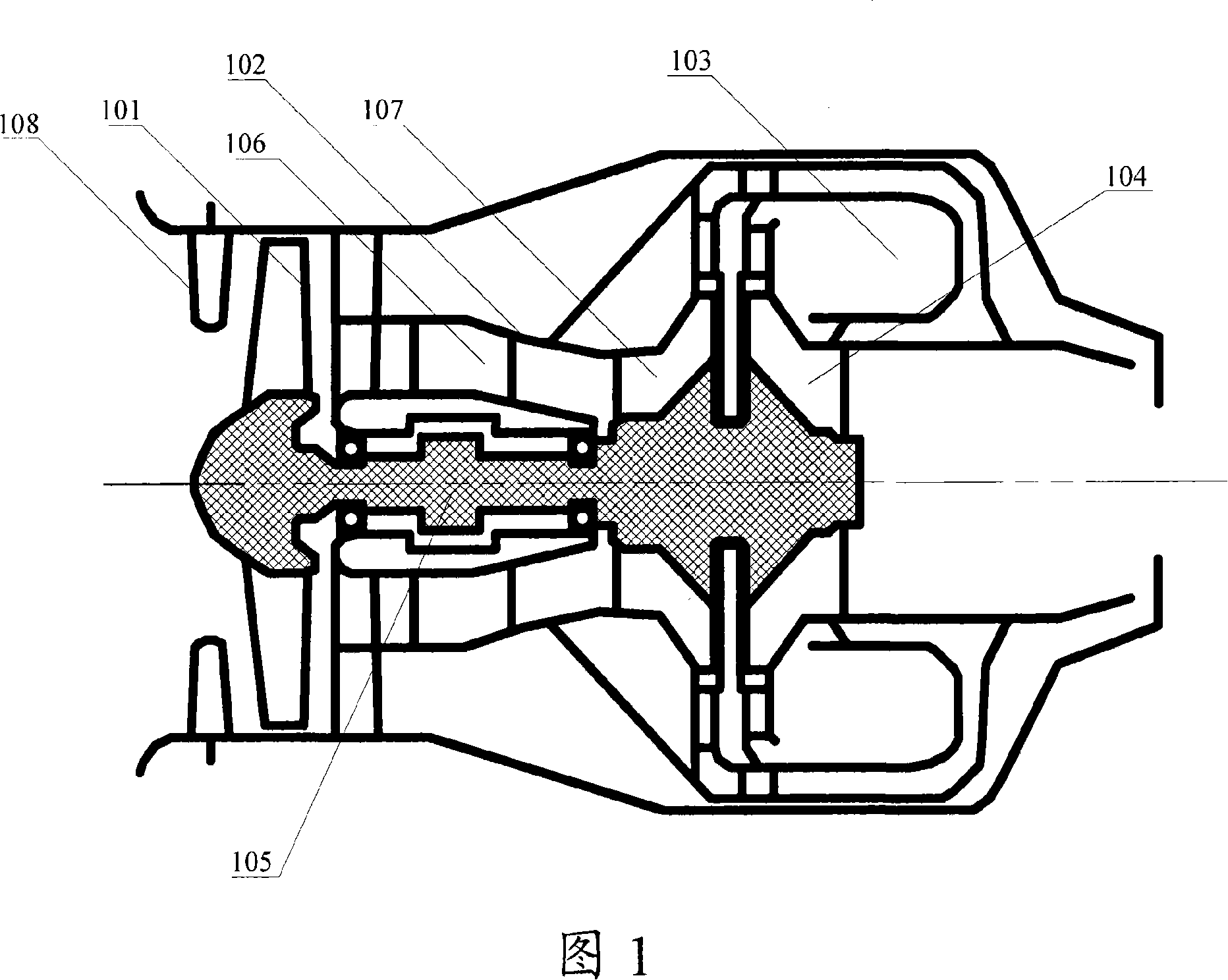
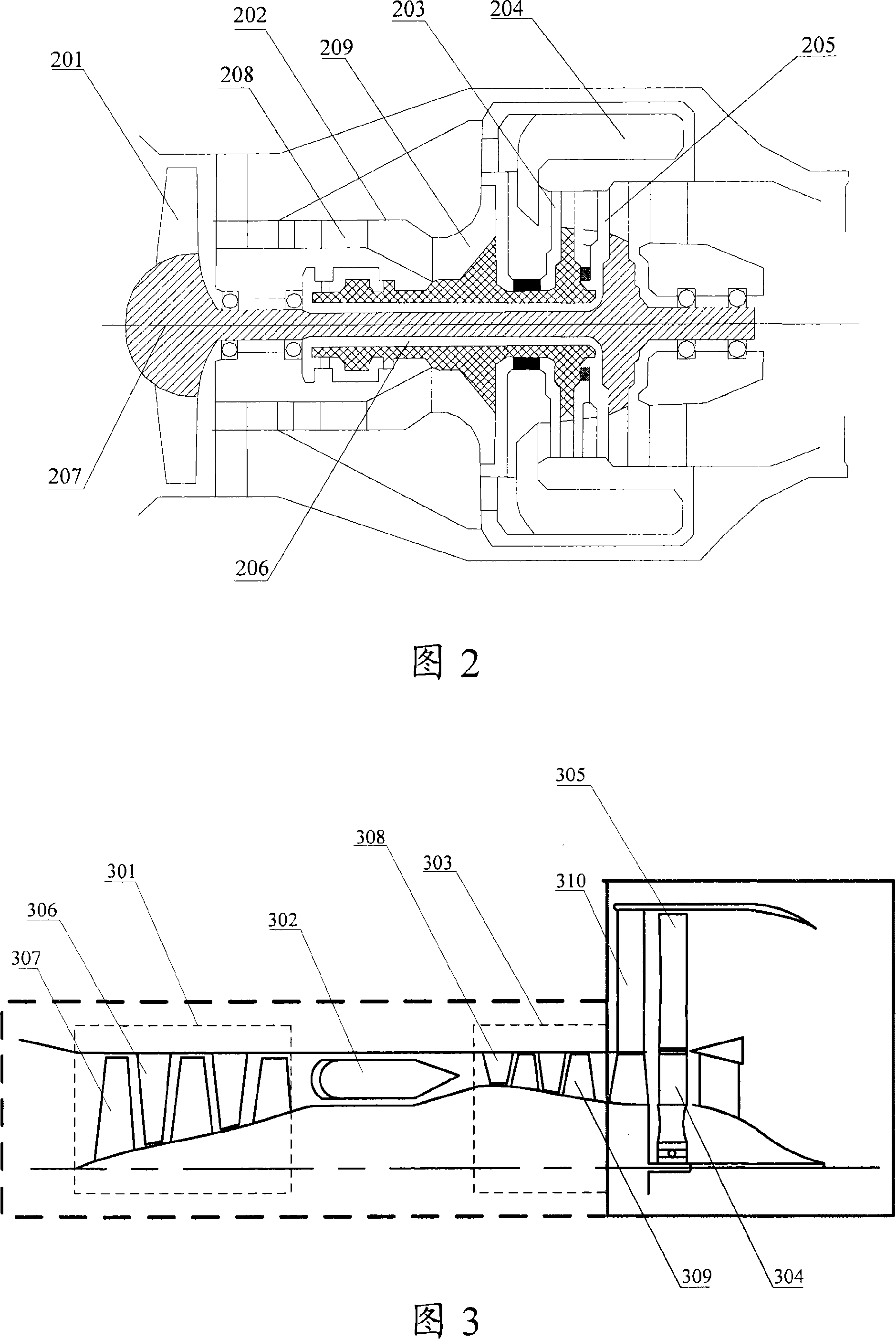
[0031] First, the turbofan engine provided by the present invention is introduced. The turbofan engine at least includes a fan and a low-pressure turbine, wherein the fan is placed at the rear of the engine and forms a unit with the low-pressure turbine.

[0032] The turbofan engine also includes a high-pressure compressor, a high-pressure turbine, a high-pressure shaft, and a combustion chamber. These components can be the same or similar to the corresponding components in a common turbojet or turbofan engine. The high-pressure compressor compresses the air entering the engine. , Forming high-temperature and high-pressure air; the combustion chamber burns the high-temperature and high-pressure air to form high-temperature and high-pressure gas; the high-temper...


PUM


Abstract

The present invention discloses one kind of turbo-fan engine includes at least one low pressure turbine and one fan in the tail of the engine to constitute one unit with the low pressure turbine and its design process. The engine structure comprising low pressure turbine and post-set fan has facilitated design, less rotor dynamic risk, less part number, raised operation reliability, lowered maintenance cost, favor to reducing axial size and overall weight and improving the thrust-weight ratio of engine. The present invention makes it possible to change available turbojet engine into turbo-fan engine.

Description

technical field [0001] The invention relates to the field of engines, in particular to a turbofan engine and a design method thereof. Background technique [0002] Turbine engine is a commonly used engine type in the engine field, and turbojet engine and turbofan engine are widely used, for example, as a missile power plant in the military field, and in automobiles and ships in the civilian field. [0003] FIG. 1 is a schematic diagram of the basic structure of a single-rotor turbofan engine in the prior art, and the end from which the airflow is ejected is called the tail. This turbofan engine comprises fan 101, compressor 102, combustion chamber 103, turbine 104 and rotating shaft 105, and compressor 102 is made up of axial flow compressor blade 106 and centrifugal compressor blade 107, and rotating shaft 105 connects fan 101, compressor 102 and turbine 104 . The turbofan engine may also include a stationary guide vane 108 in front of the fan 101 for adjusting the angle ...

Claims


Application Information

Patent Timeline
IPC IPC(8): F02K3/062F02K3/072
Inventor 徐力平邹正平刘火星
Owner BEIHANG UNIV
Why Eureka
Try Eureka