Portable handheld equipment with sliding way structure integrated with antenna functions

A handheld device and portable technology, which is applied in the direction of telephone structure, casing/cabinet/drawer parts, electrical components, etc., can solve the problems of complex antenna manufacturing process, difficult electronic equipment design, and low manufacturing yield rate. , to reduce the antenna assembly process, facilitate the layout of the motherboard space, and improve the use environment.

Inactive Publication Date: 2011-09-28
BYD CO LTD
View PDF7 Cites 3 Cited by
  • Summary
  • Abstract
  • Description
  • Claims
  • Application Information

AI Technical Summary

Problems solved by technology

The bluetooth antenna, GPS antenna, etc. are generally installed on the main board due to the small antenna body. Also due to the requirements of the antenna radiation signal, electronic components and other metal structural parts must not be arranged within 5mm around the antenna, so the main board is located on the bluetooth antenna, GPS The vicinity of small antennas such as antennas also needs clearance, and there must be no metal components such as metal shields around, which makes the design of PCB (printed circuit board) very limited and brings many difficulties to the design of electronic equipment.
On the other hand, since the main antenna etc. are generally thermally fused to the antenna bracket or attached to the housing, this makes the manufacturing process of the antenna complex, the process is too long, the production cycle is too long, and often caused by improper operation of the manufacturer. low rate problem

Method used


Image

  • Portable handheld equipment with sliding way structure integrated with antenna functions
  • Portable handheld equipment with sliding way structure integrated with antenna functions
  • Portable handheld equipment with sliding way structure integrated with antenna functions

Examples


Embodiment Construction

[0024] In order to make the object, technical solution and advantages of the present invention clearer, the present invention will be further described in detail below in conjunction with the accompanying drawings and embodiments. It should be understood that the specific embodiments described here are only used to explain the present invention, not to limit the present invention.

[0025] Since the integrated slide rail and antenna structure of the present invention can be applied to all portable handheld terminals that have signal requirements, in order to make the technical problems, technical solutions and advantages to be solved by the present invention clearer, this article temporarily takes mobile phones as specific embodiments.

[0026] The content of the present invention will be further elaborated below in conjunction with the accompanying drawings and embodiments.

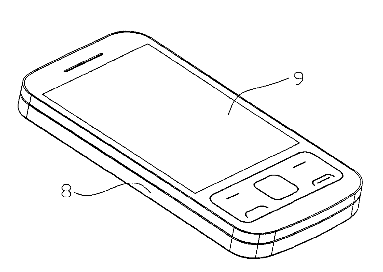
[0027] Such as Figure 1a As shown, it is an effect diagram of the mobile phone according to the embo...


PUM


Abstract

The invention provides portable handheld equipment with a sliding way structure integrated with antenna functions. The portable handheld equipment comprises a liquid crystal display (LCD) fixing bracket, a small keyboard supporting piece, a lower sliding closure component, a flexible printed circuit (FPC) component, an upper sliding closure component, a lower cover and an upper cover, wherein the lower sliding closure component is buckled with the upper sliding closure component to form a sliding way; the front end of the upper sliding closure component is provided with pored or slotted antenna characteristic body area in which feed points of an antenna are arranged; and the normal projection of the antenna characteristic body area is required to be kept completely vacant all the time. The portable handheld equipment integrates sliding way functions and the antenna functions, finishes receiving and transmitting information by the pored or slotted antenna characteristic body area formed on a sliding closure, and simultaneously, effectively improves the using environment of antenna signals because the normal projection of the antenna characteristic body area is required to be kept completely vacant all the time; and the designing of the whole equipment, particularly the spatial arrangement of a mainboard is more convenient, difficulties in the designing of the whole structure are greatly reduced, an antenna assembling process is reduced, and the production efficiency is improved.

Description

【Technical field】 [0001] The invention relates to the technical field of mobile communication, and relates to a portable hand-held device, in particular to a portable hand-held device with an antenna function on a slide rail structure. 【Background technique】 [0002] The main function of the antenna in portable communication terminals such as mobile phones is to transmit and receive signals. Due to the requirements of the signal on the design of the antenna signal, there must be no large metal parts around the antenna. Generally speaking, the main antenna of the current mobile phone is located at the lower part of the mobile phone. On the one hand, it is far away from the head, so that the radiation of electromagnetic waves to the human body is minimized. On the other hand, there is no large metal antenna at the lower end. Components can well meet the requirements of the antenna for surrounding use. The bluetooth antenna, GPS antenna, etc. are generally installed on the mai...

Claims


Application Information

Patent Timeline
Patent Type & Authority Applications(China)
IPC IPC(8): H04B1/38H04M1/02H05K5/03H04B1/3827
Inventor 周虎余传芳
Owner BYD CO LTD
Why Eureka
Try Eureka