Grating and its backlight module

A backlight module and grating technology, applied in diffraction grating, optics, optical components, etc., can solve problems such as reducing the utilization rate of light energy of liquid crystal displays

Inactive Publication Date: 2008-03-26
TSINGHUA UNIV
View PDF0 Cites 31 Cited by
  • Summary
  • Abstract
  • Description
  • Claims
  • Application Information

AI Technical Summary

Problems solved by technology

Since 2/3 of the light energy is absorbed by the color filter 10, the ligh

Method used


Image

  • Grating and its backlight module
  • Grating and its backlight module
  • Grating and its backlight module

Examples


Example Embodiment

[0030] The present invention will be further described below with reference to the drawings and embodiments.

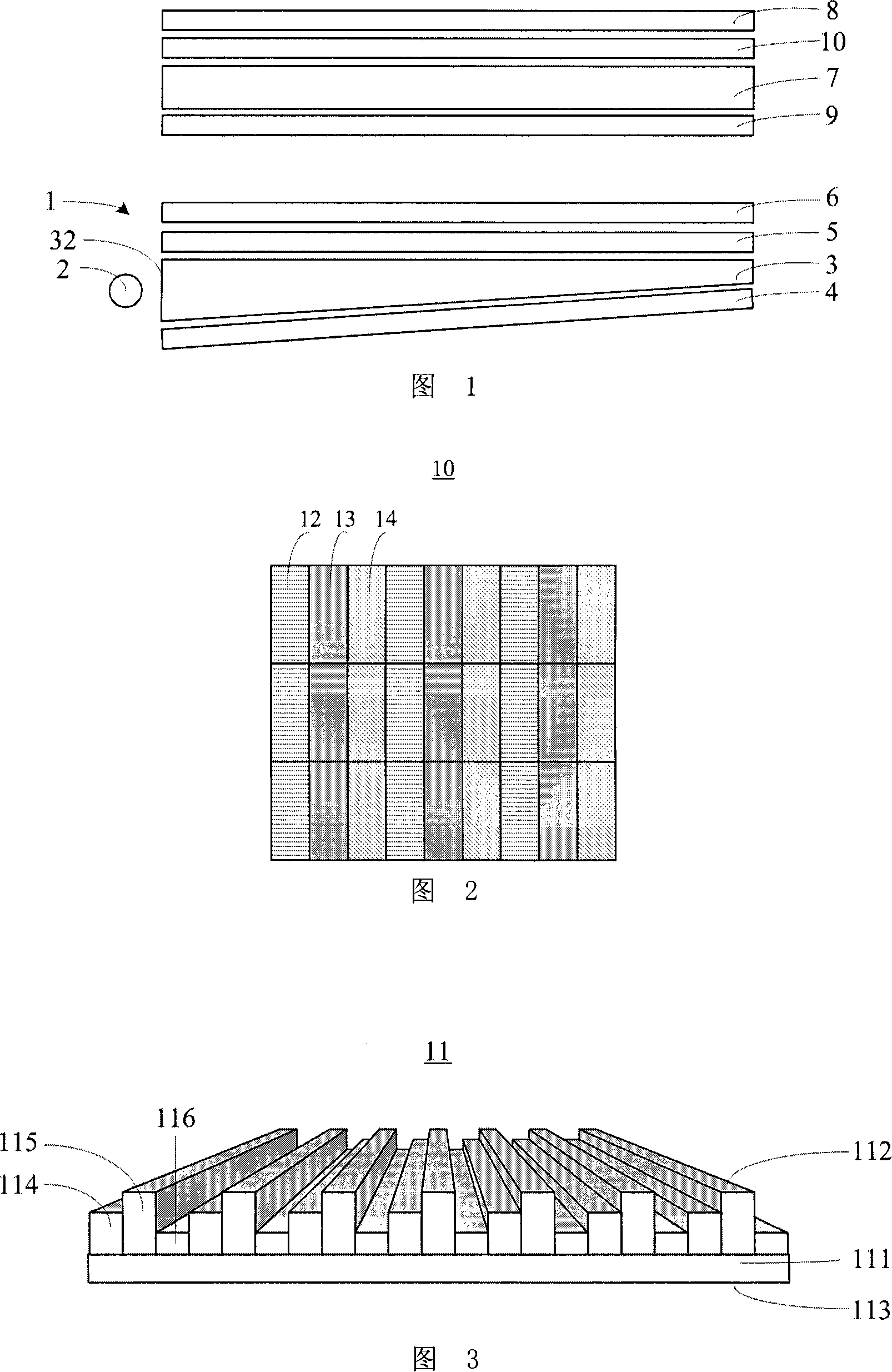
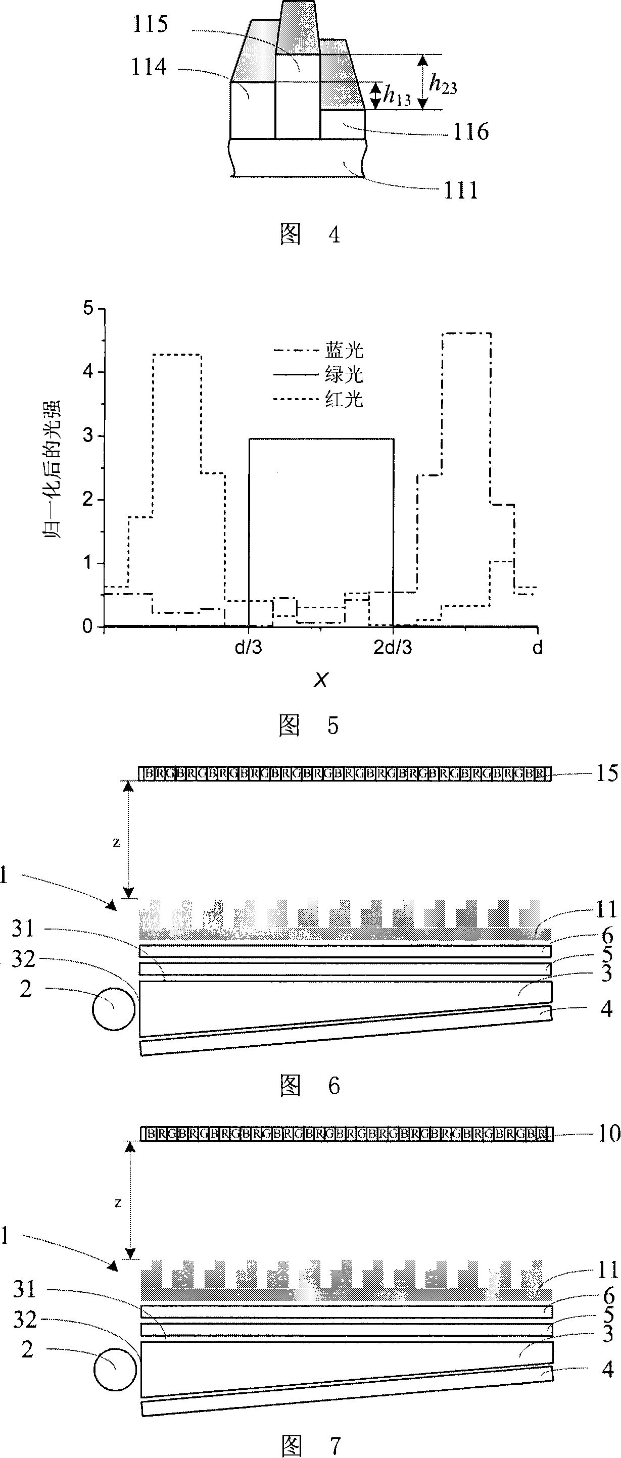
[0031] FIG. 3 is a three-dimensional schematic diagram of the grating 11 according to the first embodiment of the present invention. The grating 11 includes a base material portion 111 and a light-emitting surface 112. The substrate includes a light-incident surface 113 and side surfaces connecting the light-incident surface 113 and the light-emitting surface 112. The grating structure is an equal-period grating, and the light exit surface 112 is a stepped structure, wherein the widths of the step 114, the step 115, and the step 116 are the same. The grating 11 uses the fractional Taber effect.

[0032] Assuming n=1.52, the wavelengths of the three types of light incident at the same time during work are λ respectively b =0.45μm, λ g =0.54μm, λ r =0.63μm, the height of the three steps is h 1 =C+2.06μm, h 2 =C+3.76μm, h 3 =Cμm, where C is any positive number or 0, determin...


PUM


Abstract

A kind of grating and its negative photo mould, it belongs to the optical fluid crystal display set technology field. To solve the problem that the light energy usage of color fluid crystal display is low, this invention discloses a kind of grating and its negative photo mould, the said grating includes incident surface, the emergent surface which is relative to the incident surface and the side which connects the incident surface and the emergent surface, the grating is isochronism grating; each period of the grating has three step, the width of each step is equal; the altitude difference choice of the grating step is to make the value of sigma1,sigma2 least. The said negative photo mould includes the light source, the light plate and the said grating; the light source is set relative to the incident surface (32) of the light plate, the said light plate, grating overlays in order; this invention uses the grating to separate the color in near field based on the color separation method of diffraction optical technology, it has realized the high-usage of light energy, solved the problem that the light energy waste is large in the negative photo system, to make the incident light of the negative light source can be used, ensure the negative light source provides high efficiency light to the fluid crystal display.

Description

technical field [0001] The invention relates to a grating capable of realizing the separation of R, G, and B colors and having high utilization rate of light energy, and a backlight module using the grating, belonging to the technical field of optical liquid crystal display devices. Background technique [0002] Since the liquid crystal itself does not emit light, a backlight is required to illuminate the liquid crystal. In order to realize color display, liquid crystal display uses the method of R, G, B three primary colors to synthesize color to realize. [0003] The main structure of an existing color liquid crystal display is shown in FIG. 1 , a color liquid crystal display device is composed of a backlight module 1 , a liquid crystal display panel 7 and a color filter 10 . The backlight module 1 includes a light source 2 , a light guide plate 3 , a reflection sheet 4 , a diffusion sheet 5 and a prism sheet 6 . The upper and lower surfaces of the liquid crystal display...

Claims


Application Information

Patent Timeline
IPC IPC(8): G02B5/18G02B27/00G02F1/13357G02F1/1335
Inventor 谭峭峰张琰严瑛白金国藩
Owner TSINGHUA UNIV
Why Eureka
Try Eureka