A multi-channel clock synchronization method and system

A clock synchronization, multi-channel technology, applied in the field of methods and systems, to achieve the effect of clock

Inactive Publication Date: 2008-03-26
UNIV OF ELECTRONIC SCI & TECH OF CHINA
View PDF0 Cites 57 Cited by
  • Summary
  • Abstract
  • Description
  • Claims
  • Application Information

AI Technical Summary

Problems solved by technology

The existing technology is mostly based on the hardware circuit shown in Figure 3 in terms of hardware, that is, an analog signal reflecting phase compensation is fed into the input terminal of the loop filter in a standard phase-locked loop to adjust t

Method used


Image

  • A multi-channel clock synchronization method and system

Examples


Embodiment Construction

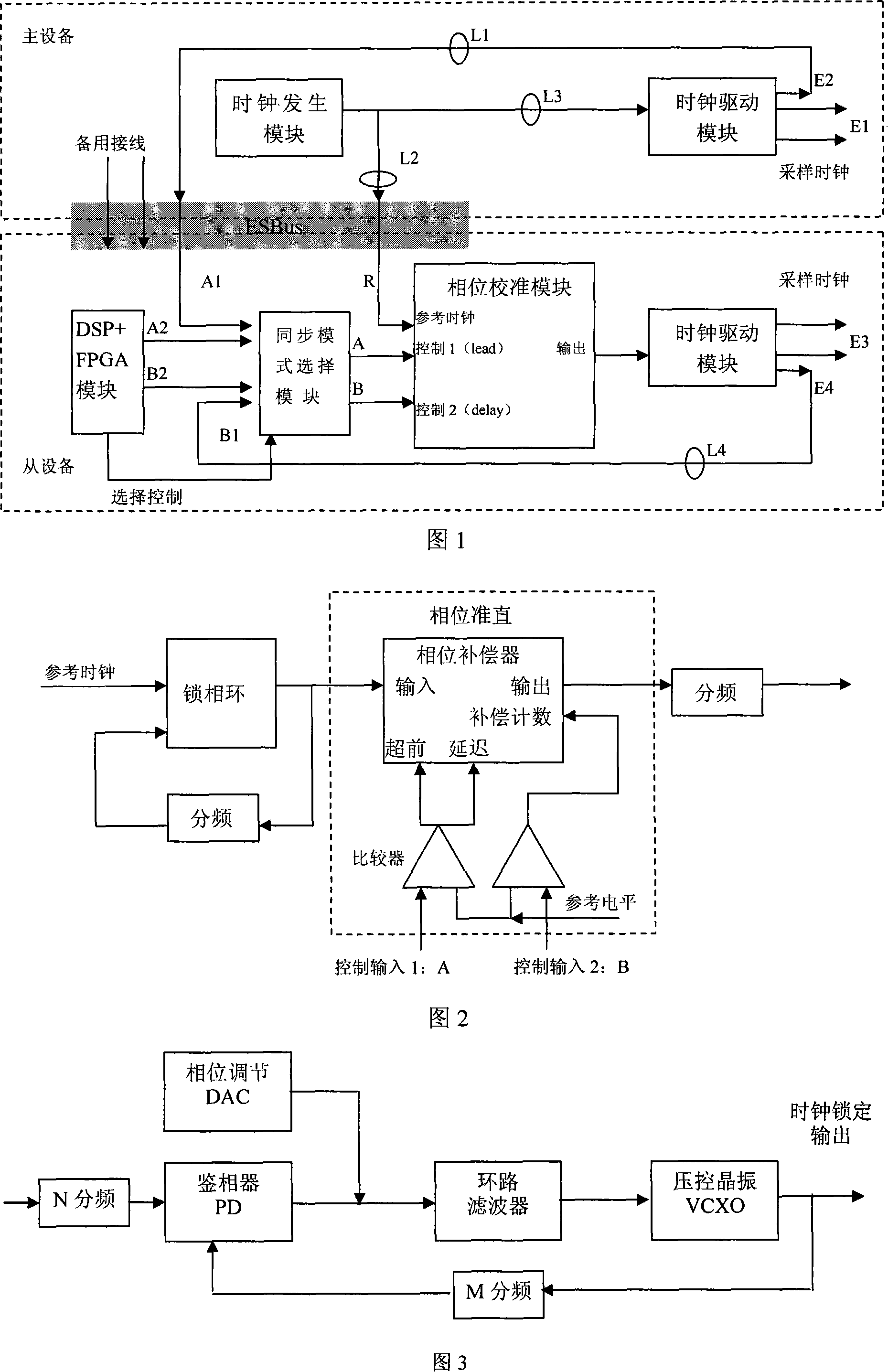
[0025] As shown in Fig. 1, the present invention mainly consists of two parts, a master device and a slave device. The master device is composed of clock generation module and clock driver module, and the slave device is composed of synchronous mode selection, phase alignment and clock drive. The master and slave devices are linked by a signal bus (ESBus).

[0026] The signal processing method for multi-channel clock synchronization is described in detail below:

[0027] 1) The clock generation module in the master device is mainly composed of a frequency synthesizer such as DDS and a phase-locked loop (PLL), which is responsible for generating the reference clock signal R of the master device and the slave device. The clock driving module drives the reference clock R to output clocks E1 and E2, wherein E1 is used as the subsequent master system sampling clock.

[0028] 2) The reference clock R and the system clock E2 generated by the master device are sent to the slave devi...


PUM


Abstract

This invention provides a multi-channel clock synchronizing method and a system, in which, a phase calibration theory is used and a phase calibration module takes received sampling clocks of a main device and a path of sampling clocks output by a drive module of a slave device as the phase calibration automatic control input signal to regulate the phase of a reference clock of the main device so as to realize accurate synchronizatin of main and slave devices, and the system includes a main device and at least one slave device and provides a DSP+FPGA module used in generating active synchronous signals and a control mode selecting module used in realizing selection of active and automatic modes, which can realize accurate synchronization of multi-channel clocks, and an operator can regulate phase difference of main and slave device actively when the clock system is lost at automatic synchronization to realize synchronization again.

Description

technical field [0001] The invention is mainly applied in the field of multi-channel signal / data generation and acquisition, and is a method and system capable of effectively ensuring the synchronous work of multi-channel data / signal generation and acquisition systems. Background technique [0002] Signal generation and data acquisition are the key elements of the test system, which are widely used in various electronics-related industries such as communication, consumer electronics, and semiconductor manufacturing. [0003] Clock synchronization technology plays an important role in multi-channel signal / data generation and acquisition systems. With the high integration of electronic systems and the increase in the operating frequency of electronic systems, traditional test and measurement instruments are often limited by the number of channels when building a test system. The limitations of multi-channel excitation sources and multi-channel responses require precise timing ...

Claims


Application Information

Patent Timeline
IPC IPC(8): H03L7/00H03L7/06
Inventor 王志刚田书林王猛师奕兵王厚军
Owner UNIV OF ELECTRONIC SCI & TECH OF CHINA
Why Eureka
Try Eureka