Driving circuit of power amplifier

A technology of power amplifier and driving circuit, applied in power amplifier, improving amplifier to improve efficiency, improving amplifier to reduce nonlinear distortion, etc., can solve problems such as linearity and efficiency need to be further improved, achieve poor quality factor and improve efficiency , the effect of high efficiency

Active Publication Date: 2008-04-02
RDA TECH
View PDF0 Cites 6 Cited by
  • Summary
  • Abstract
  • Description
  • Claims
  • Application Information

AI Technical Summary

Problems solved by technology

The disadvantages of this drive circuit are: linearity and efficiency need to be further improved, need to use a mat

Method used


Image

  • Driving circuit of power amplifier
  • Driving circuit of power amplifier

Examples


Example Embodiment

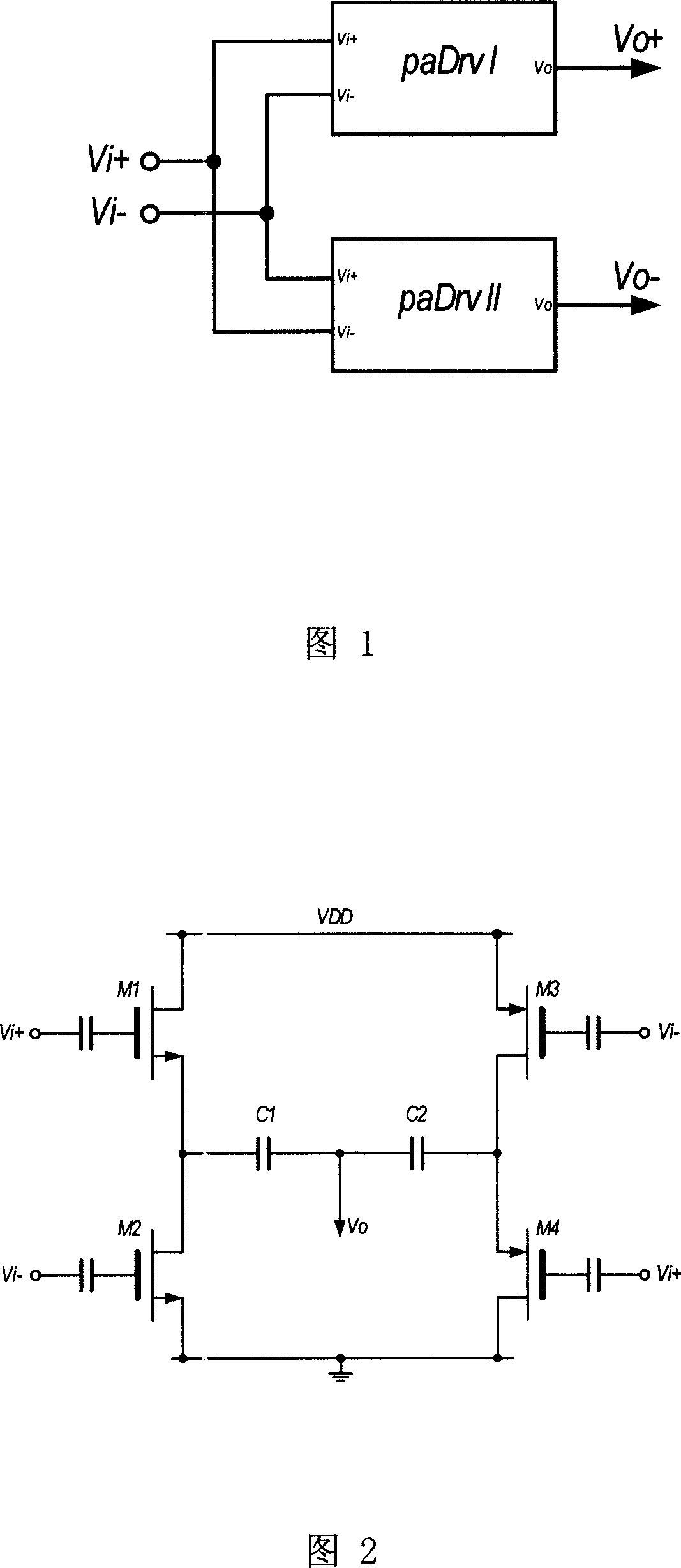
[0016] As shown in Figure 1, the power amplifier drive circuit of the present invention includes two parallel-connected power amplifier drive circuits paDrv I and paDrv II with the same double-ended input and single-ended output, and the input signals are cross-connected to form a double-ended input -Power amplifier drive circuit with double-ended output structure. That is, the output terminal Vo of the power amplifier driving circuit paDrv I is connected to the total output terminal Vo+, the input positive terminal Vi+ is connected to the total input positive terminal Vi+, and the input negative terminal Vi- is connected to the total input negative terminal Vi-; the power amplifier driving circuit paDrv The output terminal Vo of II is connected to the general output terminal Vo-, the input positive terminal Vi+ is connected to the general input negative terminal Vi-, and the input negative terminal Vi- is connected to the general input positive terminal Vi+.

[0017] The total in...


PUM


Abstract

The present invention discloses a power amplifier driving circuit which includes two parallel-connected identical double end input-single end output power amplifier driving circuit paDrvI and paDrvII, and the input signal is across connected to form a power amplifier driving circuit with the double end input-single end output structure. The invention has the advantages of wide scope of working frequency, providing enough output power, good linearity, matching the output to 50ohm and easy integrating on the chip.

Description

technical field [0001] The invention relates to a radio frequency circuit, in particular to a power amplifier driving circuit. Background technique [0002] The last stage of the transmitter is generally a power amplifier, which outputs a certain amount of power to the antenna, and then transmits it into space. The power amplifier usually has limited power gain and 50 ohm input impedance, so it is required that the circuit before the power amplifier can output enough power to drive the power amplifier to meet the transmission power requirement. The power amplifier driving circuit is a circuit for realizing the above functions. [0003] At present, the power amplifier drive circuit mainly adopts single-tube common-source amplification or double-tube cascode amplification, and then uses an inductor, or an inductor-capacitor resonance circuit, or a choke coil as a load, and finally matches it to 50 ohms through an output matching network. The disadvantages of this drive circu...

Claims


Application Information

Patent Timeline
IPC IPC(8): H03F1/02H03F1/32H03F3/20
Inventor 魏述然胡海星
Owner RDA TECH
Why Eureka
Try Eureka