Refrigerator
A technology for refrigerators and condensers, which is applied in the field of refrigerators and can solve the problems of loud resonance sound, difficulty in ensuring handling safety, and impact on energy saving.
- Summary
- Abstract
- Description
- Claims
- Application Information
AI Technical Summary
Problems solved by technology
Method used
Image

Examples
Embodiment approach 1
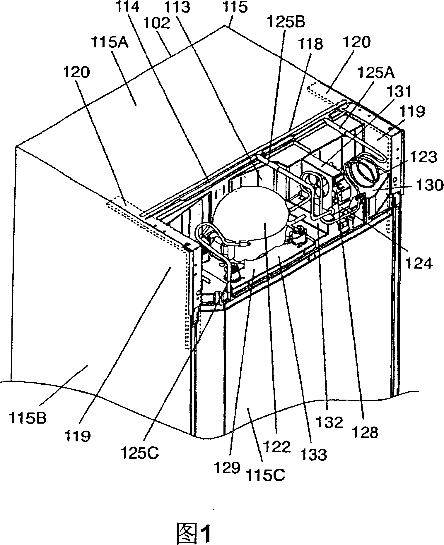
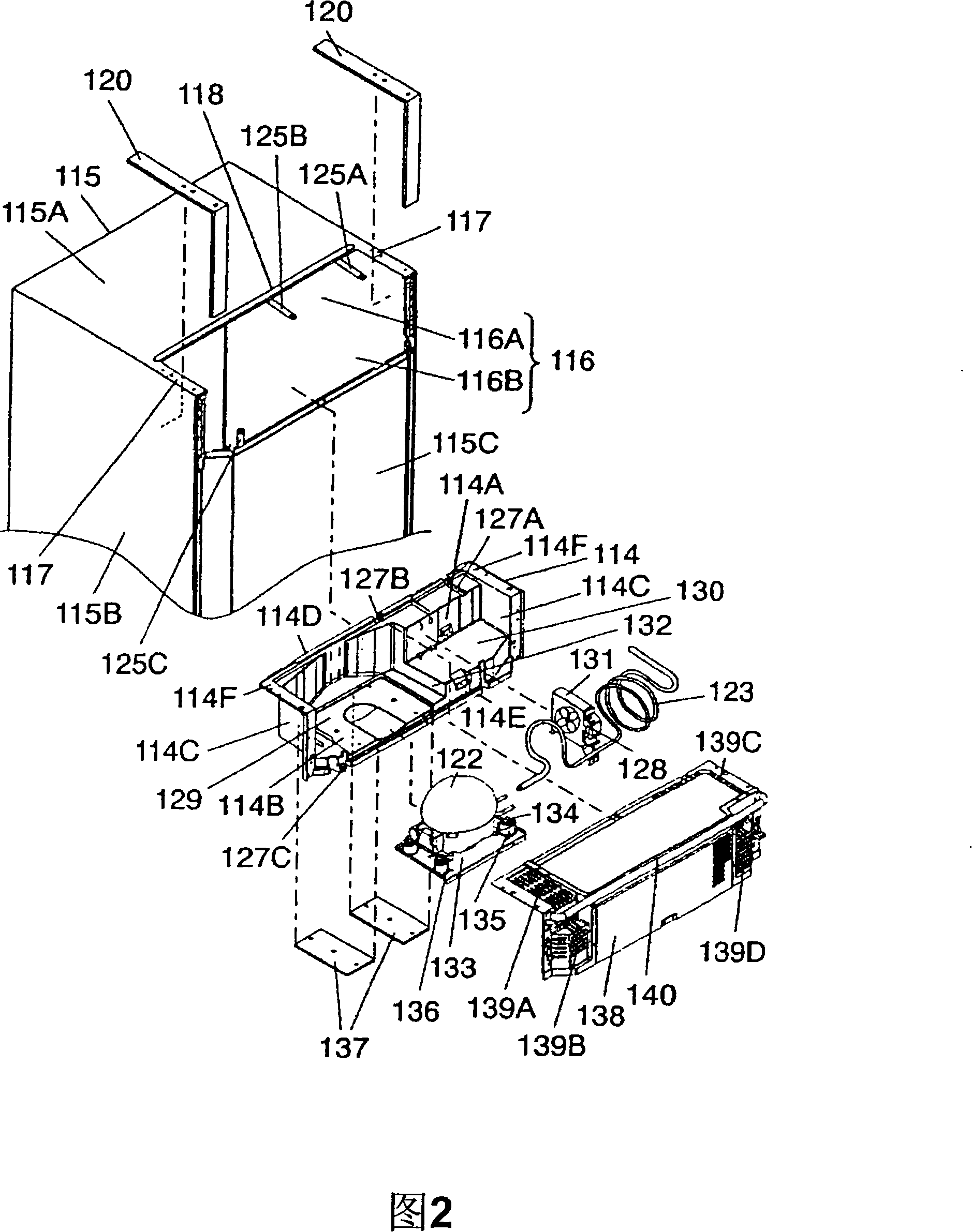
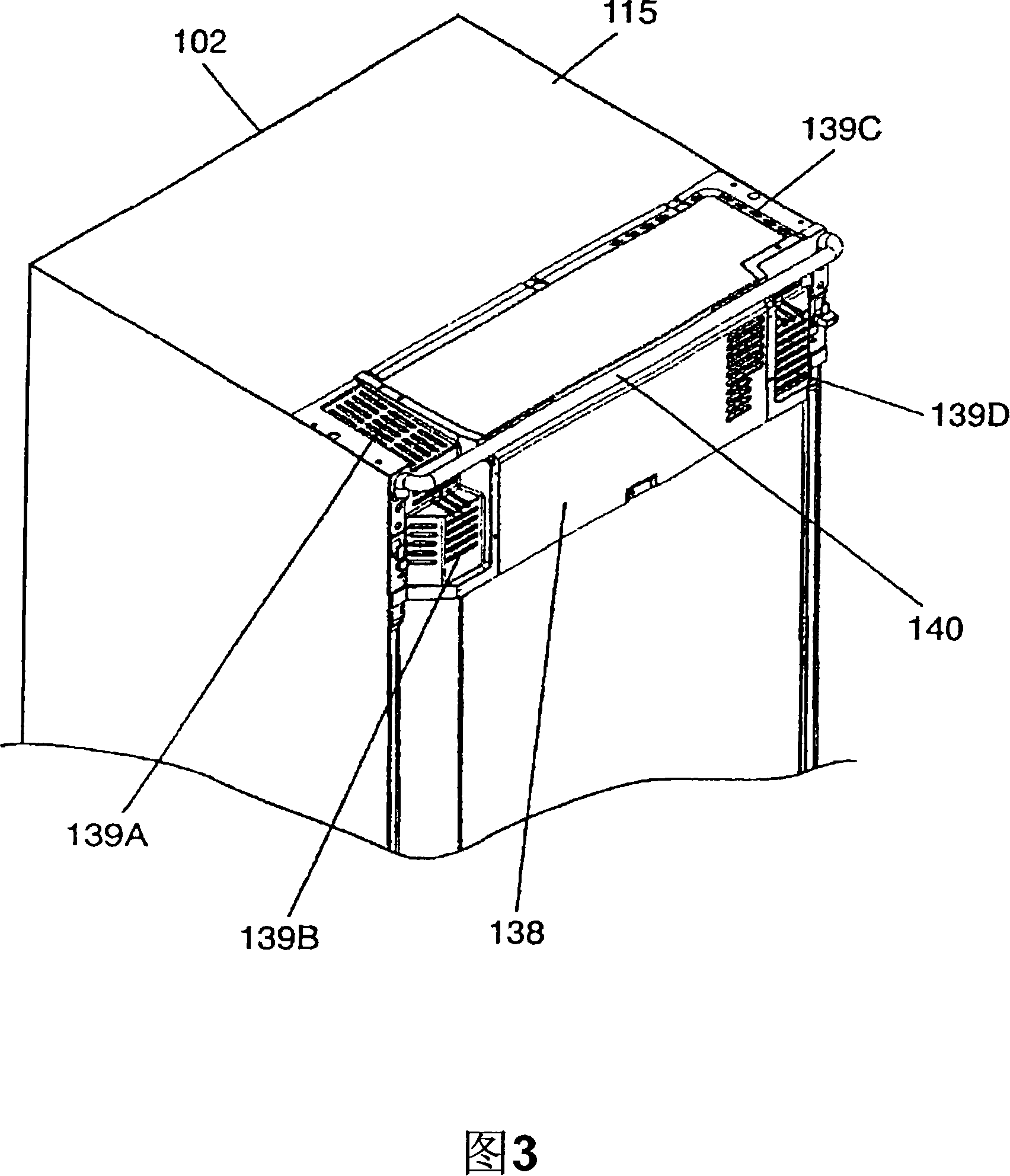
[0093] Embodiment 1 of the present invention will be described using FIGS. 1 to 5 . In the figure, the refrigerator main body 101 has a storage room divided into a plurality of regions in the heat-insulating box 102. From the top, there is a refrigerator room 103, an ice making room 104, a multifunctional room 105 and a vegetable room arranged side by side with the ice making room 104. 106. The sequence configuration of the freezer compartment 107. The multifunctional room 105 is a room for switching temperature ranges such as freezing, refrigerating, chilled, and partial freezing, or a storage room having processing functions such as cooking, heating, thawing, drying, and keeping warm.
[0094] The front opening of each store room is provided with a foam-filled heat insulating door such as polyurethane. Refrigerating room 103 is provided with doors 108A and 108B of a split type. The ice-making compartment 104, the multifunctional compartment 105, the vegetable compartment 1...
Embodiment approach 2
[0135] Embodiment 2 of the present invention will be described again using FIGS. 1 to 6 . In the drawing, a vacuum heat insulating material 201 is attached to the inner surface of both side panels 115B of the outer case with an adhesive such as hot-melt, for example. The vacuum heat insulating material 201 is also provided on the upper part of the side panels 115B, and is extended and pasted in the space 129 between the side walls 114C of the outer shell of the machine room. In addition, on the back surfaces of the respective walls 114A, 114B, and 114C of the outer shell of the machine room, a small vacuum insulating material 202 made of the same material as the vacuum insulating material 201 corresponding to each size is pasted. The vacuum heat insulating material 122 does not necessarily have to be installed on the entire surface of the walls 114A, 114B, and 114C of the outer shell of the machine room. It is only necessary to select an appropriate installation position in co...
Embodiment approach 3
[0143] Embodiment 3 will be described again using FIGS. 1 to 7 . As shown in the figure, the outer box 301 is composed of a top panel 303 , a back panel 304 , and two side panels 305 respectively.
[0144] By overlapping the concave portion 302 with the outer frame 114 of the machine room made of resin, a considerable part of the machine room becomes a double structure of steel plate and resin, which improves the structural strength. Furthermore, considering the joint structure of both flexible members and the like, it is possible to suppress transmission of vibration and noise of the compressor 122 and the air blower 128 .
[0145] In addition, since the method of inserting the outer frame 114 of the machine room made of resin without forming a cutout in a corresponding part of the machine room, there is no need to worry about the sealing structure of the foamed heat insulating material 121 at the junction around the cutout.
[0146] In addition, at least the side panels 305...
PUM
 Abstract
Description
Claims
Application Information
 - R&D
- Intellectual Property
- Life Sciences
- Materials
- Tech Scout
- Unparalleled Data Quality
- Higher Quality Content
- 60% Fewer Hallucinations
Browse by: Latest US Patents, China's latest patents, Technical Efficacy Thesaurus, Application Domain, Technology Topic, Popular Technical Reports.
© 2025 PatSnap. All rights reserved.Legal|Privacy policy|Modern Slavery Act Transparency Statement|Sitemap|About US| Contact US: help@patsnap.com