

Magnetic core and application article using it
A technology of magnetic cores and products, applied in the direction of magnetic cores/yokes, transformer/inductor magnetic cores, magnetic materials, etc., can solve the problems of low magnetostriction, unrealized, larger magnetic cores, etc.
- Summary
- Abstract
- Description
- Claims
- Application Information
AI Technical Summary
Problems solved by technology
Method used
Image

Examples
Embodiment 1
[0032] Amorphous alloy strips with a thickness of 23 to 25 μm and a width of 5 mm were prepared by the following steps: Prepare 200 g of composition Fe 82 Si 2 B 13.9 C 2 mn 0.1 the master alloy; the master alloy was heated to 1300° C. with high-frequency power to melt it and prepare a molten alloy; and, the molten alloy was sprayed onto a Cu—Be alloy roll rotating at 25 to 30 m / s. will be used to blow CO 2 The nozzle of the gas is installed at a position 10 cm away from the exhaust nozzle of the Cu roller in the rear direction, so that the gas used for blowing CO 2 The gas jets formed an angle of 45 degrees with respect to the surface of the roll. In regulating CO 2 The blowing pressure of the gas, and while controlling the gas pressure near the roll at the exhaust nozzle to 0 (unblown gas), 0.1 and 0.3 MPa, the amorphous alloy was cast. Then, it was found that the oxygen concentrations in the vicinity of the exhaust nozzle (within 3 cm from the position where the molt...
Embodiment 2
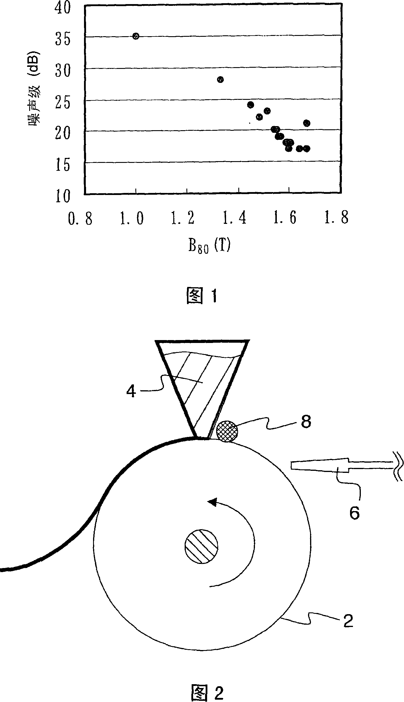
[0040] 200 g of master alloys with the composition shown in Table 3 were prepared, and then by steps similar to those in Example 1, an amorphous alloy strip with a width of 5 mm was prepared and the inner diameter / outer diameter was measured to be 25 / 35 mm properties of the toroidal core. Properties are shown in Table 3. By using GD-OES (Glow Discharge Optical Emission Spectrometer) manufactured by Horiba, Ltd., elements were quantitatively analyzed to measure the position of the carbon segregation layer from the rolling surface in the depth direction. As a result, a portion having a higher carbon concentration than the uniform concentration in the inside is regarded as a carbon segregation layer, and the position where the concentration is highest and the concentration value are read as the position of the carbon segregation layer and the value of the carbon peak. It is understood that the noise level is related to B 80 Highly correlated, can be increased by increasing B s...
Embodiment 2-2
[0044] Amorphous alloy ribbons having the compositions shown in Table 4 were prepared in a similar manner to the case of Example 1, and properties of toroidal cores with inner / outer diameters of 25 / 35 mm were measured. Properties are shown in Table 4. The addition of 4% carbon increases the iron loss of the amorphous alloy strip due to the increase in coercive force, and may cause problems in the manufacturing step due to the brittleness of the amorphous alloy strip. The addition of 0.7 atomic % of Mn makes B s decrease, decrease in squareness, increase in coercive force, and increase in iron loss. Large additions of both carbon and Mn also increase the noise level.
[0045] [Table 4]
[0046] sample
PUM
| Property | Measurement | Unit |
|---|---|---|
| The inside diameter of | aaaaa | aaaaa |
Abstract
Description
Claims
Application Information